Bridge crane hoisting safety anti-collision system and method based on dynamic binocular vision

A binocular vision system, bridge crane technology, applied in safety devices, transportation and packaging, load hanging components, etc., can solve the problems of high safety risk, difficult to grasp the timing of emergency stop, etc., to reduce complexity and improve reliability. The effect of robustness and robustness

Active Publication Date: 2021-02-26
中国人民解放军火箭军工程大学
3 Cites 8 Cited by

AI-Extracted Technical Summary

Problems solved by technology

[0003] The purpose of the present invention is to provide a safety collision avoidance system and method for hoisting bridge cranes based on dynamic binocular...

Method used

2. utilize histogram equalization method to enhance image contrast;
Adopting SURF feature point matching method is to match by the Euclidean distance between two feature points, because its feature vector is 64 dimensions, so can effectively improve the computing efficiency of matching;
Along with the continuous development of computer vision technology, vision sensor has obtained more and more widely application in various electromechanical systems, binocular vision sensing has advantages such as high efficiency, suitable precision, simple system structure, low cost, Widely used in online, non-contact product inspection and quality control at manufacturing sites. In the measurement of moving objects (including animals and human body), since the image acquisition is completed in an instant, it is an effective measurement method. During the operation of the bridge crane, the binocular vision system is used to complete the detection of moving objects and the three-dimensional reconstruction of the hoisting space, and calculate the operation information, position information, and scale information of the load and obstacles online to predict collisions and decide whether to use deceleration , steering or emergency braking to realize the safe operation of the crane.
S101, utilize dynamic threshold value method ...

Abstract

The invention provides a bridge crane hoisting safety anti-collision system and method based on dynamic binocular vision, and the method is based on a binocular vision measurement system and comprisesthe following steps: 1, constructing three-dimensional point cloud information of a target; 2, reconstructing a static obstacle in a crane working scene to obtain a reference sample set; 3, collecting image information of the crane in the load transferring process, comparing the image information with the reference sample obtained in the step 2, and respectively obtaining three-dimensional coordinates of the load and the dynamic obstacle; 4, predicting whether the load collides with the dynamic obstacle or the static obstacle or not according to the three-dimensional coordinates of the load and the dynamic obstacle obtained in the step 3; and 5, controlling the operation of the crane according to the judgment result. According to the method, binocular vision is applied to bridge crane hoisting safety collision avoidance, non-contact performance and high robustness are achieved, the complexity degree of an anti-collision system can be reduced to a large extent, and the working reliability of the system is improved.

Application Domain

Image enhancementImage analysis +2

Technology Topic

Collision systemEngineering +5

Image

  • Bridge crane hoisting safety anti-collision system and method based on dynamic binocular vision
  • Bridge crane hoisting safety anti-collision system and method based on dynamic binocular vision
  • Bridge crane hoisting safety anti-collision system and method based on dynamic binocular vision

Examples

  • Experimental program(1)

Example Embodiment

[0059]The present invention will be further described in detail below in conjunction with the accompanying drawings.
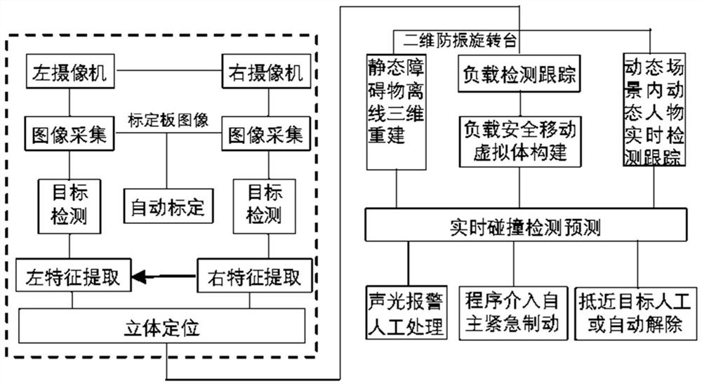
[0060]With the continuous development of computer vision technology, vision sensors have been widely used in various electromechanical systems. Binocular vision sensors have the advantages of high efficiency, appropriate accuracy, simple system structure, and low cost, and are widely used in Online, non-contact product testing and quality control at the manufacturing site. In the measurement of moving objects (including animals and human bodies), since the image acquisition is completed in an instant, it is an effective measurement method. During the operation of the bridge crane, the detection of moving objects and the three-dimensional reconstruction of the hoisting space are completed through the binocular vision system, and the operation information, position information, and scale information of the load and obstacles are calculated online to predict the collision and decide whether to use deceleration , Steering or emergency braking to realize the safe operation of the crane.
[0061]Such asfigure 1 As shown, the present invention provides a bridge crane hoisting safety anti-collision system based on dynamic binocular vision. Aiming at large scenes of bridge cranes and large-scale load hoisting conditions, the system installs binocular cameras on the crane bridge to form Mobile dynamic binocular vision measurement system. The binocular vision system is used for the three-dimensional reconstruction of the load, static and dynamic objects in the working environment, dynamic target detection and tracking, and collision pre-detection to complete emergency treatment.
[0062]specifically:
[0063]Such asfigure 1 As shown, the bridge crane hoisting safety collision avoidance system includes a dynamic binocular vision system, a processing unit, and an alarm unit. The dynamic binocular vision system is installed on the crane bridge and used to collect image information of the crane hoisting work scene , And transmit the collected image information to the processing unit; the processing unit is used to process the received image information, detect moving objects (people or other obstacles) that suddenly break into the work space in real time, and predict the load at the same time Whether it collides with static obstacles and moving obstacles in the working space, and transmits the predicted result to the alarm unit; the alarm unit is used to act as an alarm prompt according to the predicted result.
[0064]The bridge crane structure includes a crane beam 1, a trolley 2, a lifting device 3, and a bridge frame 4, wherein the bridge frame 4 is a trolley running track of the bridge crane, which is installed on the load-bearing column of the factory building; the crane beam 1 is installed on the bridge 4; the trolley 2 is installed on the crane beam 1 and moves back and forth; the lifting device is installed on the trolley 2.
[0065]The dynamic binocular vision system includes a binocular camera 5 and a two-dimensional rotating head 6, wherein the binocular camera 5 is installed on a two-dimensional rotating head 6; the two-dimensional rotating head 6 is suspended by vibration isolation The bracket 7 is hung down on one end of the crane beam 1 to realize synchronous movement with the crane beam 1.
[0066]The binocular camera 5 includes a first camera and a second camera, wherein the two cameras are placed in parallel left and right, and the distance between the two cameras is the baseline length, which can be adjusted during the experiment.
[0067]The alarm unit includes a PLC control module, wherein the PLC control module is connected to the bridge crane electric bell, the crane trolley frequency converter, the crane trolley frequency converter, and the crane hoisting frequency converter.
[0068]The invention provides a bridge crane hoisting safety and collision avoidance method based on a dynamic binocular vision system, which specifically includes the following steps:
[0069]Step 1. Collect the image of the calibration board, use the calibration algorithm to process the collected image of the calibration board to obtain the internal and external parameters of the binocular camera; use the dynamic binocular vision system to collect the image information of the crane hoisting work scene, and compare each frame of image The information is processed to obtain feature points, and the three-dimensional point cloud information of the target (static obstacle in the image) is constructed according to the feature points;
[0070]Step 2: According to the 3D point cloud information of the target obtained in step 1, static obstacles in the crane work scene are reconstructed to obtain a reference sample set;
[0071]Step 3: Collect the image information of the crane transfer load process in real time, and process each frame of the collected image information, and then compare it with the reference sample obtained in step 2 to obtain the three-dimensional coordinates of the load and the dynamic obstacle respectively;
[0072]Step 4. Predict whether the load will collide with the dynamic obstacle or the static obstacle according to the three-dimensional coordinates of the load and the dynamic obstacle respectively obtained in step 3;
[0073]Step 5: Control the operation of the crane according to the judgment result.
[0074]Among them, in step 1, the image of the calibration plate is collected, specifically:
[0075]Will be likeFigure 4 The metal calibration board is placed between the first camera and the second camera; the left and right camera images of the calibration board are obtained by the first camera and the second camera, and then the calibration board is continuously moved to different positions in the camera's field of view. Take at least 20 sets of pictures at an angle for calibration to obtain the internal and external parameters of the binocular vision system.
[0076]Use the calibration algorithm to process the collected images of the calibration board. The specific method is as follows:
[0077]S101: Perform threshold segmentation on the collected calibration plate image by dynamic threshold method to obtain a binary image; apply a geometric shape-based filtering method to process the image after threshold segmentation, filter out most of the isolated points, and better protect Target points are set to reduce the influence of noise on calibration and improve the adaptability of the working environment;
[0078]S102: Perform image edge extraction on the binary image obtained in S101 by using mathematical morphology, and perform closing operation, Otsu threshold segmentation, and contour extraction on the image in order to obtain a continuous, smooth, and noise-free contour curve; For each obstacle, find the smallest ellipse that can wrap its contour curve, and use the edge information of the elliptical target to replace the obstacle;
[0079]S103, multi-target contour tracking and target screening
[0080]The general contour tracking algorithm can only track the edge of a single target. There are multiple ellipse targets here, and a multi-target contour tracking algorithm is designed to automatically track all the target ellipse edge information. At the same time, for some special curves, such as ellipses with broken lines, a two-way tracking method is adopted to ensure that the correct results can be obtained when processing the point sets of these special elliptic curves, making it more robust. At the same time, filter according to the position information and pixel number of each target, and sort the required target ellipses to form a one-to-one correspondence with the characteristic circle in the calibration image, and prepare for the calibration solution;
[0081]S104, feature extraction:
[0082]In the image acquisition process, due to the influence of the camera position and its own distortion and other factors, the circle on the calibration board will generally become an ellipse in the calibration image, but there is a definite projection relationship between the center point of the ellipse and the center point of the circular hole; Therefore, the center point of the ellipse is the feature point to be extracted.
[0083]Use the edge point data of the ellipse on the image obtained by S103 to fit the ellipse equation, and use the least square method to obtain the computer frame-stored coordinates of the center of the ellipse. The specific algorithm is as follows:
[0084]The general equation of an ellipse is:
[0085]Ax2+2Bxy+Cy2+2Dx+2Ey+F=0 (1)
[0086]Substitute the detected edges into equation (1) to form a transcendental equation group, and then use the optimization method to solve the best fitting parameters A, B, ..., F in the sense of least squares, then the center of the ellipse (X0,Y0The coordinates of) are:
[0087]
[0088]S105, two-step calibration:
[0089]Substituting the three-dimensional space coordinates of the feature points and the corresponding two-dimensional computer frame storage coordinates into the camera model, the calibration of the camera can be completed according to the RAC two-step method, and the camera including focal length, principal point coordinates, skew coefficient and distortion can be obtained. Internal parameters and external parameters including rotation matrix and translation matrix. The calibration of the external parameters is mainly used to describe the relative pose relationship between the camera coordinate system and the world coordinate system, and the calibration of the internal coordinate system is mainly to correct the error of the camera's geometric optics.
[0090]In step 1, the dynamic binocular vision system is used to collect the image information of the crane hoisting work scene, and the image information of each frame is processed to obtain the feature points. The specific method is:
[0091]S1011: Perform denoising, equalization, matching and sharpening methods on the collected images of crane hoisting work scenes in order to obtain preprocessed images;
[0092]The pretreatment is carried out in sequence according to the following steps:
[0093]①Using image mean filtering and Gaussian filtering methods to remove image noise;
[0094]②Use histogram equalization method to enhance image contrast;
[0095]③Use the histogram matching method to balance the brightness difference;
[0096]④Using the Laplace sharpening method to enhance the edge details of the image.
[0097]S1012: Perform feature point detection on the preprocessed image obtained in S1011 using the SURF algorithm to obtain feature points;
[0098]The specific steps for feature point detection are:
[0099]① Construct Hessian matrix;
[0100]②Tectonic scale space;
[0101]③Accurately locate feature points
[0102]④ Feature point matching;
[0103]⑤ Generate feature point descriptors.
[0104]The SURF feature point matching method uses the Euclidean distance between two feature points to match. Since its feature vector is 64-dimensional, it can effectively improve the calculation efficiency of matching;
[0105]Elimination of mismatched points: The matching results often have many mismatches. In order to eliminate these errors, use the KNN algorithm to find the two features that best match the feature. If the matching distance of the first feature is less than the matching distance of the second feature If the ratio is less than a certain threshold, the match is accepted, otherwise it is regarded as a mismatch.
[0106]Through this step, the corresponding relationship between the feature points of the same target in the two images taken by the binocular camera can be obtained, and the disparity map of the left image can be obtained at the same time, so as to lay the foundation for the next step to construct the obstacle 3D point cloud information through the geometric method basis.
[0107]In step 1, construct the 3D point cloud information of the target according to the feature points, the specific method is:
[0108]Use the 3D reconstruction SFM algorithm to obtain the 3D point cloud information of the target; among them, the SFM algorithm includes the following four steps:
[0109]① Estimate the basic matrix F: use the RANSAC method to estimate E, and use the 8-point method to solve the problem during each iteration;
[0110]②Matrix essence estimation E: The eigen matrix has 7 independent parameters. The purpose of estimating the essence matrix is ​​to constrain the matching obtained before, and obtain the matching relationship between the projection points of the same space point on different images;
[0111]③The essential matrix SVD is decomposed into rotation matrix R and translation matrix T;
[0112]④ Calculation of three-dimensional point cloud: The present invention uses the triangle method to solve the problem. According to the transformation matrix R and T between the two cameras and the coordinates of each pair of matching points, the method restores the matching points based on the known information In three-dimensional space
[0113]Coordinates, by the formula:
[0114]x·S=K·(R·X+T)
[0115]Where x and S are the unknowns in the equation, use S to make the cross product on both sides of the equation, and then eliminate S, we get:
[0116]0=x·K·(R·X+T)
[0117]Further derivation can be obtained:
[0118]
[0119]Use the singular value decomposition method to find the zero space of the matrix on the left of X, and then normalize the last element to 1, then X can be found. Its geometric meaning is equivalent to making extension lines of corresponding points on the two-dimensional image plane from the optical centers of two cameras. The point where the two extension lines intersect is the solution of the equation, that is, the corresponding point on the actual object point in the three-dimensional space. Get the three-dimensional information of the target.
[0120]In step 2, construct static obstacles in the crane work scene to obtain benchmark samples. The specific method is:
[0121]S201. Since the disparity map contains three-dimensional information, on the basis of the disparity map of the left image, accumulate the number of pixels C having the same horizontal disparity on each row of the disparity imagep, And record the point with the largest X coordinate value among all the points with the same horizontal parallax in the row, and use this point as the new pixel coordinate, and CpA new gray value for the pixel, thus forming a V-disparity map;
[0122]Accumulate the number of pixels with the same horizontal disparity in each column of the parallax image, and record the point with the largest Y coordinate value among all the points with the same horizontal disparity in the column, and use this point as the new pixel coordinate, and the number of pixels is this The new gray value of the pixel, thus forming a U-disparity map;
[0123]The calculation of the V-disparity map is to project the plane in the original image as a straight line. For obstacles, the plane can be projected as an oblique line and a line segment perpendicular to the oblique line, that is, the obstacle detection is converted from plane detection For line segment detection, the next step is to extract line segments in the V-disparity map by introducing a straight line detection algorithm.
[0124]S202: Extract a straight line in the V-disparity map by using a Hough transform straight line detection algorithm, and obtain the contact point of the obstacle from the intersection of the two line segments.
[0125]The height of the vertical straight line segment represents the height of the obstacle, and the width can be obtained through the U-disparity map. The calculation process of the U-disparity map is similar to that of the V-disparity map. The difference is that the V-disparity map accumulates the same pixels in the horizontal direction. The U-disparity map is the accumulation of the same number of pixels in the vertical direction.
[0126]Combining the V-disparity map and the U-disparity map can accurately extract the width, height, and touch point of the obstacle in the target image to be detected, and then lock the obstacle area.
[0127]Then according to the three-dimensional point cloud information of the target calculated in step 1, the static obstacles in the crane work scene can be obtained, that is, the reference sample can be obtained.
[0128]In step 3, the collected image information is processed and compared with the reference sample obtained in step 2 to obtain the dynamic detection target; this step is used to obtain the dynamic target within the camera's field of view. Among the existing algorithms, the gray-scale detection algorithm under monocular vision can detect relatively accurate contour edges, while the parallax-based detection algorithm under binocular vision can correctly detect moving targets, which is suitable for targets and backgrounds with similar gray However, since the estimation of the disparity map inside the object is more accurate, the estimation accuracy at the edge is slightly worse. Therefore, the present invention adopts a continuous inter-frame difference algorithm combining grayscale and parallax for the detection of dynamic targets such as lifting loads and entering the field of view, such asFigure 6 Shown, where fl(k-l)And flkRefer to the k-1th frame and the kth frame obtained by the left camera respectively; fr(k-l)And frkRefer to the k-1th frame and the kth frame obtained by the right camera respectively; dk-1And dkRefer to the disparity map of the k-1th frame and the kth frame obtained after stereo matching respectively; f′l(k-l)And d′k-1Respectively refer to the image after global motion compensation, ie, correction, of the disparity map corresponding to the k-1 frame and the k-1 frame obtained by the left camera; the specific method is:
[0129]S301, using such asPicture 9The global motion model parameter estimation algorithm shown in the k-th frame image f taken by the left cameralkAnd the k-1th frame image fl(k-l)Perform processing to obtain parameter estimation results;
[0130]Use asFigure 8 The shown global motion compensation algorithm combined with the parameter estimation results on the k-1th frame image f taken by the left cameral(k-l)Perform motion compensation to obtain the corrected image f′ of the k-1 frame of the left cameral(k-l);
[0131]The image f′ after the correction of the k-1 frame of the left cameral(k-l)Subtract the gray value of the corresponding pixel point of the k-th frame image of the left camera to obtain the gray level difference map between consecutive frames;
[0132]S302: Perform stereo matching on the k-1 frame image of the left camera and the k-1 frame image of the right camera to obtain a disparity map of the k-1 frame image after stereo matching;
[0133]Use asFigure 8 The shown global motion compensation algorithm combines the parameter estimation results to perform motion compensation on the disparity map of the k-1th frame image after stereo matching, to obtain the disparity map of the k-1th frame image after correction;
[0134]Perform stereo matching on the k-th frame image of the left camera and the k-th frame image of the right camera to obtain a disparity map of the k-th frame image after stereo matching;
[0135]Subtracting the disparity values ​​of the corresponding pixel points of the disparity map after stereo matching of the k-th frame image and the disparity map after stereo matching of the k-1 frame image to obtain the disparity difference map between consecutive frames;
[0136]S303, directly multiplying the gray-scale difference image between consecutive frames and the disparity difference image between consecutive frames to obtain a continuous inter-frame difference image combining grayscale and disparity;
[0137]S304, while taking a new frame of image, use the parameter estimation result obtained in S301 to perform motion compensation on the reference sample obtained in step 3 to obtain an updated reference sample;
[0138]S305: Subtract the continuous inter-frame difference image that combines grayscale and disparity obtained in S303 from the gray value of the corresponding pixel of the updated reference sample obtained in S304 to obtain the area where the moving target is located; adopt the maximum inter-class variance method Perform binarization, morphological filtering, and connectivity analysis on the full image of the area where the moving target is located, and obtain the three-dimensional coordinates of the load and dynamic obstacles respectively;
[0139]At the same time, the updated reference samples are processed to obtain feature points, and the three-dimensional coordinates of static obstacles are obtained according to the feature points.
[0140]Among them, the present invention applies morphological filtering processing to solve the problems that there are many isolated points and holes in the target area, fractures will occur at the edges, and random noise points that obey the Gaussian distribution in the background area.
[0141]The existing morphological filtering methods include expansion, corrosion, opening operations and closing operations; the present invention first performs the opening operation and then the closing operation, and subsequently, since the obtained target information is incomplete, the expansion operation is appropriately performed.
[0142]Target connectivity analysis is a key step for target recognition and feature extraction. Therefore, the present invention finally uses a sequential algorithm based on eight connectivity to judge each point from top to bottom and from left to right, and then compare it with the predetermined target Compared with the size of, think that it is less than the size of the target as a misjudgment, and the other is to detect the correct target, calculate the number of targets, and the geometric center and connected domain size of each target. The calculation formula of the geometric center is as follows:
[0143]
[0144]Where (xo,y0,z0) Is the coordinates of the geometric center, (xi,yi,zi) Is the coordinates of pixels in the same connected domain, and N is the total number of pixels in the same connected domain.
[0145]In step 4, predict whether the load will collide with a dynamic obstacle or a static obstacle according to the three-dimensional coordinates of the load and the dynamic obstacle respectively obtained in step 3. The specific method is:
[0146]S401, using the CamShift tracking algorithm to track the three-dimensional coordinates of the load and the dynamic obstacle obtained in step 3, and obtain the current position information of the load and the dynamic obstacle respectively;
[0147]S402, using the Kalman filter algorithm to predict the next moment position information of the load and the dynamic obstacle in combination with the current position information of the load and the dynamic obstacle respectively obtained in S401;
[0148]In S403, the collision detection algorithm based on the directional bounding box (OBB) is used to combine the load predicted in S402 with the next moment position information of the dynamic obstacle to predict in real time whether the load collides with the dynamic obstacle or the static obstacle.
[0149]Among them, in S403, using the directional bounding box (OBB) collision detection algorithm combined with the predicted position information of the dynamic target detection object at the next moment, real-time prediction of whether the dynamic target detection object collides with other obstacles, the specific method is:
[0150]S5031, collision model establishment
[0151]The collision cuboid of loads and static and dynamic obstacles constructed based on the OBB bounding box can be represented by a center point, a third-order direction matrix and three 1/2 side lengths, where the third-order direction matrix represents the directions of the three axes of the bounding box. By calculating the three eigenvectors of the covariance matrix C and matrix C of all triangle vertices in the bounding box, the directions of the three axes of the OBB bounding box can be obtained.
[0152]Specifically, for static obstacles, you can use the point cloud information reconstructed by the three-dimensional matching object to construct the OBB model; for load and dynamic obstacles, you can use the load and dynamic obstacle center obtained by Kalman filtering as well as the load and obstacle Size, and further build the OBB model. At this time, for the load, in order to leave a safety margin, on the basis of the load OBB model, the same size is increased in the 6 directions (x, -x, y, -y, z, -y), increasing by 800mm and 1000mm respectively The load-moving virtual body 1 and the load-moving virtual body 2 are formed to correspond to different treatment methods. The schematic diagram is as followsFigure 7 Shown.
[0153]S4032, triangle intersection test
[0154]For the load moving virtual body and the static and dynamic obstacle OBB bounding box, the intersection test of the two triangles formed between the respective vertices is the key point. Although a large number of disjoint triangles between the models can be excluded, in many cases, the necessary Intersection test between triangles. The test between triangles can be roughly divided into three stages. The first stage is to detect whether any triangle B of the load virtual body and the plane of the obstacle OBB bounding box triangle A are intersected, and if they intersect, the intersecting line segment is calculated; in the second stage, the plane is divided according to the line where the two sides of the triangle A are located. A is divided into 4 parts, and it is judged whether the two triangles are separated according to the distribution of the line of intersection in plane A; the third stage is to further analyze the situation that the second stage cannot judge the separation between the triangles, and check whether the line of intersection and triangle A intersect. If the line of intersection and triangle A intersect, triangles A and B intersect, otherwise, triangles A and B separate.
[0155]In step 5, the operation of the crane is controlled according to the judgment result, specifically:
[0156]If it is predicted that a collision may occur, the crane will turn on the voice alarm prompt, manually dispose of it or start an autonomous emergency braking strategy to achieve a rapid and effective stop of the crane and avoid collisions between loads and obstacles; specifically:
[0157]When the distance between the dynamic target detection object and other obstacles is less than or equal to 1000mm, the detection signal is sent to the PLC, and the electric bell is controlled to send an early warning bell to alarm, and the operator will slow down or change direction;
[0158]When the distance between the dynamic target detection object and other obstacles is less than or equal to 800mm, a signal is sent to the PLC to control the frequency converter to achieve emergency braking of the crane.
[0159]If it is predicted that a collision is unlikely, the crane continues to operate normally.
[0160]In still another embodiment of the present invention, a bridge crane hoisting safety collision avoidance system based on a dynamic binocular vision system is provided, which can be used to realize the above-mentioned bridge crane hoisting safety collision avoidance method based on the dynamic binocular vision system , Including acquisition module, reconstruction module, processing module, prediction module and alarm module; among them,
[0161]The acquisition module is used to collect the image information of the crane hoisting work scene through the dynamic binocular vision system to obtain two image information, and then process the two image information separately to obtain the feature point pairs corresponding to the static obstacles in the two images. Construct 3D point cloud information of static obstacles in the image according to the feature point pairs;
[0162]The reconstruction module is used to reconstruct the static obstacles in the crane work scene according to the three-dimensional point cloud information of the static obstacles to obtain the reference sample;
[0163]The processing module is used to collect the image information of the crane transfer load process through the dynamic binocular vision system, and process each frame of image information, and then compare it with the reference sample to obtain the three-dimensional coordinates of the load, dynamic obstacle and static obstacle respectively ;
[0164]The prediction module is used to predict whether the load will collide with the dynamic obstacle or the static obstacle according to the three-dimensional coordinates of the load, dynamic obstacle and static obstacle, and obtain the prediction result;
[0165]The alarm module is used to control the operation of the crane according to the judgment result. If the prediction result is that a collision will occur, the crane will turn on the voice alarm prompt; if it is predicted that the collision will not occur, the crane will continue to operate normally.

PUM

no PUM

Description & Claims & Application Information

We can also present the details of the Description, Claims and Application information to help users get a comprehensive understanding of the technical details of the patent, such as background art, summary of invention, brief description of drawings, description of embodiments, and other original content. On the other hand, users can also determine the specific scope of protection of the technology through the list of claims; as well as understand the changes in the life cycle of the technology with the presentation of the patent timeline. Login to view more.

Similar technology patents

Wide-area damping control method for DFIG and SSSC coordination power system

ActiveCN109659955Asimple methodRobust
Owner:STATE GRID HEILONGJIANG ELECTRIC POWER CO LTD ELECTRIC POWER RES INST +1

Image noise level estimation method based on deep learning

InactiveCN107993200ARobustAccurately estimate the effect
Owner:TIANJIN UNIV

Open-circuit fault detection method of three-phase inverter power tube

InactiveCN111537914AReduce troubleshooting costsRobust
Owner:JIANGSU UNIV

Classification and recommendation of technical efficacy words

  • Robust
  • reduce complexity

Identifying software execution behavior

ActiveUS20130185798A1reduce complexity
Owner:ACCESSDATA GRP INC

Thin client intelligent transportation system and method for use therein

InactiveUS20080114530A1reduce complexityelimination of map integrity issue
Owner:PETRISOR GREGORY C +2

Superposition coding

Owner:MOTOROLA MOBILITY LLC

MIMO PGRC system and method

ActiveUS20060250941A1reduce complexity
Owner:TEXAS INSTR INC
Why Eureka
Try Eureka