Eureka AIR delivers breakthrough ideas for toughest innovation challenges, trusted by R&D personnel around the world.

An explosion-proof power junction box

An explosion-proof power supply and junction box technology, applied in electrical components, separation methods, dispersed particle separation, etc., can solve the problems of explosion at joints, inconvenient installation and disassembly of junction boxes, safety accidents, etc., and achieve convenient installation and disassembly. The effect of reducing work intensity and increasing work efficiency

Active Publication Date: 2022-02-22
安徽欧瑞热控科技有限公司
View PDF13 Cites 0 Cited by
  • Summary
  • Abstract
  • Description
  • Claims
  • Application Information

AI Technical Summary

Problems solved by technology

The junction box in the prior art usually uses a plurality of fixing screws to fix the junction box somewhere. This method not only requires workers to carry a large number of tools for fixed installation, but also when the junction box needs to be inspected and repaired, the worker We need to disassemble a plurality of fixing screws one by one, which increases the work strength of the workers, takes time and effort, is not convenient for installing and disassembling the junction box, reduces the work efficiency of the workers, and the junction box in the prior art The internal structure is relatively simple. When the external environment is humid, the external water vapor is likely to enter the inside of the junction box body. When the external environment is cold, the water vapor condenses into water droplets, which may drip on the power cord. Connectors, thus causing damage to the interface of the power cord, resulting in the failure of the power cord and the junction box to work normally. At the same time, a short circuit may occur at the connector, causing a fire and explosion, which may cause safety accidents to outside workers. question

Method used


Image

  • An explosion-proof power junction box
  • An explosion-proof power junction box
  • An explosion-proof power junction box

Examples


Embodiment 1

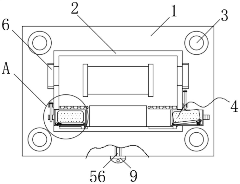
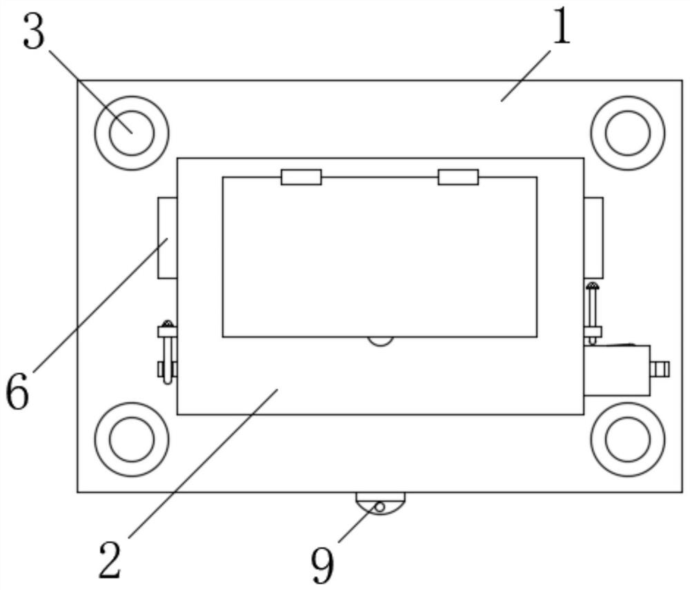
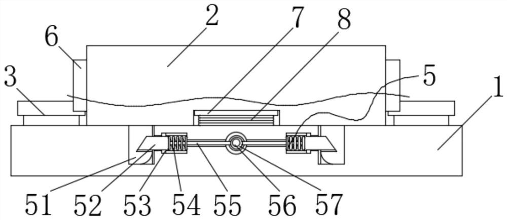
[0028] Such as Figure 1-4 As shown, the present invention provides an explosion-proof power supply junction box, including: a mounting plate 1, a junction box body 2, a replacement mechanism 4 and a buckle mechanism 5; the front of the mounting plate 1 is detachably connected to the junction box body 2, so The front of the mounting plate 1 is provided with two left-right symmetrical grooves, and a buckle mechanism 5 is provided in the two grooves. The left and right sides of the junction box body 2 are provided with placement holes, and the placement holes are provided with Replacement mechanism 4; the buckle mechanism 5 includes a mounting block 51, a clamping block 52, a second slider 53, a third spring 54 and a wire 55; wherein, the back of the junction box body 2 is fixedly connected with two mounting blocks 51. The two mounting blocks 51 are respectively arranged in the two grooves, and the adjacent surfaces of the inner walls of the two grooves are provided with a first...

Embodiment 2

[0038] Such as image 3 As shown, this embodiment provides an explosion-proof power supply junction box. The difference from Embodiment 1 is that a first spring 8 is fixedly connected to the front of the mounting plate 1, and a pressure plate 7 is fixedly connected to the other end of the first spring 8. , the front of the pressing plate 7 is attached to the back of the junction box body 2 .

[0039] In practical application, when workers disassemble the junction box body 2, when the two blocks 52 no longer limit the slot, the junction box body 2 will automatically pop up under the action of the resilience of the first spring 8, which is convenient The work of the workers has been improved, and the work efficiency of the workers has been increased.

Embodiment 3

[0041] Such as image 3 As shown, this embodiment provides an explosion-proof power supply junction box. The difference from Embodiment 1 is that the side of the installation block 51 close to the block 52 is arranged in an arc shape, and the faces away from the two blocks 52 are evenly spaced. Set on a slope.

[0042] In practical applications, during installation, workers only need to directly align the installation block 51 with the groove, and press it downwards, and the two clamping blocks 52 will approach each other under the action of the inclined surface, so that workers When installing the junction box, there is no need to twist the torsion ring 9, only need to press directly to fix it, which facilitates the installation work of the workers and reduces the work intensity of the workers.

[0043] Working principle, workers can install the installation plate 1 on the place where the junction box body 2 is needed through the installation seat 3, and then place the insta...


PUM


Abstract

The invention relates to the technical field of power supply wiring, and specifically discloses an explosion-proof power supply junction box; comprising: a mounting plate, a junction box body, a replacement mechanism and a buckle mechanism; the front of the mounting plate is detachably connected to the junction box body, the There are two symmetrical grooves on the front of the installation plate, and a buckle mechanism is arranged in the two grooves, and placement holes are arranged on the left and right sides of the junction box body, and a replacement mechanism is arranged in the placement holes; By setting the buckle mechanism, the mounting base and the mounting plate, the workers can install the mounting plate on the place where the junction box body is needed through the mounting base, so that it can pop out from the mounting plate, so that the workers can remove it without carrying a large number of disassembly tools. The junction box body is taken out, so that the junction box body is detected and maintained, which facilitates workers to install and disassemble the junction box body, reduces the work intensity of the workers, and increases the work efficiency of the workers.

Description

technical field [0001] The invention relates to the technical field of power supply wiring, and more specifically relates to an explosion-proof power supply junction box. Background technique [0002] The junction box is one of the electrical accessories. In electrical engineering, the power cord used for engineering passes through the wire tube, and the junction box of the wire is used as a transition. The junction box can protect the wire and the joint. , thus playing the role of protection and control circuit. The junction box in the prior art usually uses a plurality of fixing screws to fix the junction box somewhere. This method not only requires workers to carry a large number of tools for fixed installation, but also when the junction box needs to be inspected and repaired, the worker We need to disassemble a plurality of fixing screws one by one, which increases the work strength of the workers, takes time and effort, is not convenient for installing and disassembli...

Claims


Application Information

Patent Timeline
Patent Type & Authority Patents(China)
IPC IPC(8): H02G3/08B01D53/26
CPCH02G3/08H02G3/088B01D53/26
Inventor 王跃
Owner 安徽欧瑞热控科技有限公司
Why Eureka
Eureka Blog
Learn More