Eureka AIR delivers breakthrough ideas for toughest innovation challenges, trusted by R&D personnel around the world.

Cascading equipment

A device and cascading technology, applied in the Internet field, can solve the problems of cascading system bit error rate, packet error rate and packet loss rate increase, network link service interruption, cascading system link interruption, etc., to reduce disconnection. risk, ensure normal operation, improve reliability and stability

Active Publication Date: 2021-02-26
INSPUR SUZHOU INTELLIGENT TECH CO LTD
View PDF8 Cites 0 Cited by
  • Summary
  • Abstract
  • Description
  • Claims
  • Application Information

AI Technical Summary

Problems solved by technology

When the LOS signal of the optical module takes effect, the cascaded device cannot receive the signal, and the link of the entire cascaded system is interrupted.
When the receiving optical power of the optical module is too low, the cascaded equipment cannot receive signals normally, and the bit error rate, packet error rate, and packet loss rate of the entire cascaded system will increase
The cascading device is located in the middle of the network, and physically plays the role of connecting the upstream device and the downstream device. Once the cascading device in the middle fails or cannot receive and process data, it will directly cause the entire network link service to be interrupted.

Method used


Image

  • Cascading equipment
  • Cascading equipment
  • Cascading equipment

Examples


Embodiment Construction

[0055] In order to enable those skilled in the art to better understand the solution of the present invention, the present invention will be further described in detail below in conjunction with the accompanying drawings and specific embodiments. Apparently, the described embodiments are only some of the embodiments of the present invention, but not all of them. Based on the embodiments of the present invention, all other embodiments obtained by persons of ordinary skill in the art without making creative efforts belong to the protection scope of the present invention.

[0056] The terms "first", "second", "third" and "fourth" in the specification and claims of this application and the above drawings are used to distinguish different objects, rather than to describe a specific order . Furthermore, the terms "comprising" and "having", and any variations thereof, are intended to cover a non-exclusive inclusion. For example, a process, system, product, or device comprising a se...


PUM


Abstract

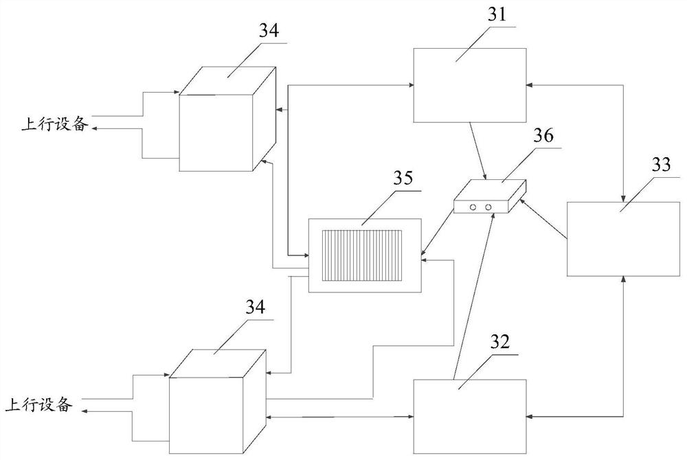
The invention discloses cascading equipment which comprises a light splitting module, an optical channel conversion assembly and a gating mode controller, wherein the normal working starting moment ofthe gating mode controller is earlier than the normal working starting moment of a central processing unit. The light splitting module divides the optical signal of ta uplink device and a downlink device into two parts, which are respectively transmitted to the optical channel conversion assembly and the corresponding optical module. The optical channel conversion assembly is, based on the connection relationship among pins, and the connection relationship among the pins, the power supply and the ground, in an internal connection mode or an external connection mode. The gating mode controllercomprises a power supply signal, a CPU state, an optical module LOS signal, optical module receiving optical power information and a connection relationship among pins of the optical channel change assembly, and controls the optical channel change assembly to be in a corresponding working mode by controlling the connection relationship among the pins in the optical channel change assembly, a power supply and the ground. Therefore, when the cascading equipment is in an abnormal state, effective emergency processing is realized for the whole cascading system, normal operation of the cascading system is guaranteed, and reliability and stability of the whole cascading link are improved.

Description

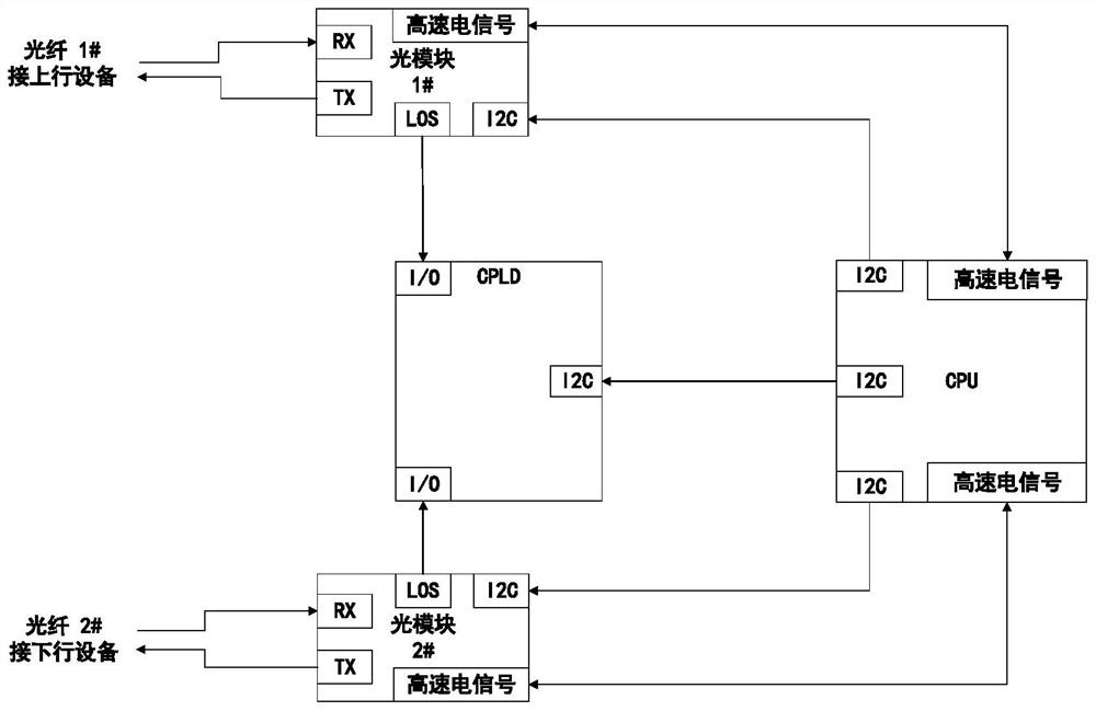
technical field [0001] The present application relates to the technical field of the Internet, in particular to a cascading device. Background technique [0002] With the development of Internet technology, the scale of the network is getting larger and larger, and the current networking methods of servers and network processing equipment are also various. As a relatively common networking method, cascading is widely used in server networking and network processing. The device is in the network. [0003] Cascading means that the output of one system is used as the input of another system, and the cascading equipment of the entire system using the cascading method can be called a cascading system. In a cascaded system, the intermediate device that connects the upstream device and the downstream device is called a cascaded device. In the cascade system, the optical module is used as the cascade device to connect the uplink device and the downlink device, such as figure 1 an...

Claims


Application Information

Patent Timeline
Patent Type & Authority Applications(China)
IPC IPC(8): H04B10/038H04B10/25
CPCH04B10/038
Inventor 黄炎坡
Owner INSPUR SUZHOU INTELLIGENT TECH CO LTD
Why Eureka
Eureka Blog
Learn More