Powder milling device for chemical production

A chemical production and powder grinding technology, which is applied in the direction of cleaning methods using tools, cleaning methods and utensils, chemical instruments and methods, etc., can solve the problem that powder is not easy to fall and collect, the effect of grinding powder is general, and the surface cleaning operation of rolling parts is inconvenient and other problems, to achieve the effect of enhancing the cleaning effect and avoiding partial rolling

Pending Publication Date: 2021-03-02
尹家琴
View PDF6 Cites 5 Cited by
  • Summary
  • Abstract
  • Description
  • Claims
  • Application Information

AI Technical Summary

Problems solved by technology

[0005] In order to overcome the disadvantages of existing milling devices, such as simple structure, average milling effect, inconvenient cleaning operation on the surface of rolling parts, and difficulty in falling and collecting

Method used


Image

  • Powder milling device for chemical production
  • Powder milling device for chemical production
  • Powder milling device for chemical production

Examples


Embodiment 1

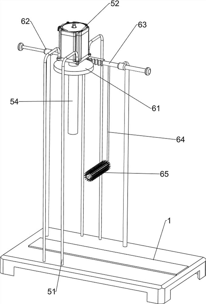
[0026] A milling device for chemical production, such as figure 1 As shown, it includes a base 1, a sliding frame 2, a slide rail frame 3, a feeding frame 4, a grinding mechanism 5, a cleaning mechanism 6 and a rotating mechanism 7. The sliding frame 2 is provided on the base 1, and the front and rear sides There are two slide rail frames 3 in lateral symmetry, and the upper parts of the four slide rail frames 3 are slidingly provided with a discharge frame 4, the left side of the base 1 is provided with a grinding mechanism 5, and the left side of the upper rear part of the base 1 is provided with a cleaning mechanism. Mechanism 6, the cleaning mechanism 6 is connected with the grinding mechanism 5, and the upper front part of the base 1 is provided with a rotating mechanism 7, and the rotating mechanism 7 is connected with the cleaning mechanism 6.

[0027] When chemical production requires grinding, this milling device can be used. First, people put the chemical raw materia...

Embodiment 2

[0029] On the basis of Example 1, such as figure 2 , image 3 and Figure 4 As shown, the grinding mechanism 5 includes a support column 51, a motor 52, a first L rod 53, a rotating shaft 54, a roller 55, a first moving block 56 and a pressure hammer 57. Support column 51, motor 52 is installed between the tops of four support columns 51, the first L bar 53 is arranged on the left side on the base 1, the output shaft of motor 52 is connected with rotating shaft 54, and the lower part of rotating shaft 54 ​​rotates with the first L bar 53 top type connection, the middle part of the rotating shaft 54 ​​is provided with a roller 55, the upper right side of the roller 55 is slidingly provided with a first moving block 56, and the bottom of the first moving block 56 is provided with a pressing hammer 57, and the pressing hammer 57 is connected with the upper right side of the first L bar 53. Sliding connection.

[0030] After starting the motor 52, the output shaft of the motor...

Embodiment 3

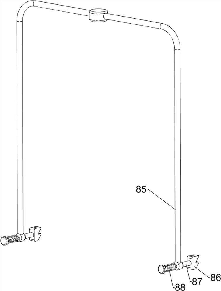
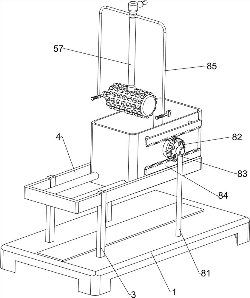
[0036] On the basis of Example 2, such as Figure 5 , Figure 6 and Figure 7 As shown, a moving mechanism 8 is also included. The front and rear sides of the base 1 are provided with a moving mechanism 8. The moving mechanism 8 is connected with the discharge frame 4. The moving mechanism 8 includes a bracket 81, a ratchet 82, a second missing tooth gear 83, The second tooth bar 84, the second L bar 85, the ratchet 86, the first slide bar 87 and the first spring 88, the front and rear sides on the base 1 are all provided with supports 81, and the two supports 81 tops are all rotatably provided with ratchets 82, the tops of the two brackets 81 are all rotatably provided with a second toothless gear 83, the second toothless gear 83 is located inside the ratchet 82, the upper and lower parts of the front wall of the discharge frame 4 and the upper and lower parts of the rear wall of the discharge frame 4 are both The second tooth rack 84 is symmetrically arranged, and the two ...


PUM


Abstract

The invention relates to a powder milling device, in particular to a powder milling device for chemical production. The invention provides the powder milling device for chemical production, which is delicate, is better in powder milling effect, automatically cleans the dust on the surface of a milling part, and is beneficial for powder collection. The powder milling device for chemical productioncomprises a base, a grinding mechanism and a clearing mechanism, wherein a slide frame for collecting powder-shaped chemical raw materials is arranged on the base in a sliding mode; the grinding mechanism for chemical raw material grinding is arranged on the base; the clearing mechanism for clearing accumulated powder on the grinding mechanism is arranged on the base; and the clearing mechanism isconnected to the grinding mechanism. A first movable block slides up and down along a roller to drive a pressure hammer to slide up and down, and the pressure hammer cracks the chemical raw materialsin a discharge frame below while moving downwards, so that the effect of grinding the chemical raw materials is achieved.

Description

technical field [0001] The invention relates to a milling device, in particular to a milling device for chemical production. Background technique [0002] Grinding equipment is widely used in the grinding process of mineral materials in metallurgy, chemical industry, mining and other fields. In the process of chemical production, it is necessary to grind chemical raw materials into powder so that the raw materials can fully contact each other and make them react more fully. However, the existing milling device has a simple structure and general milling effect, and large chemical raw materials need to be ground many times before they can be made into powder, which increases the labor intensity and production cost of the operator. The accumulated powder on the pressing roller will affect the rolling effect of the rolling machine, and it is inconvenient to manually clean the surface of the rolling roller. [0003] Patent application CN211099492U, the publication date is 2020.0...

Claims


Application Information

Patent Timeline
IPC IPC(8): B02C1/14B02C23/00B08B1/00B08B1/04
CPCB02C1/14B02C23/00B08B1/002B08B1/008B08B1/04
Inventor 尹家琴
Owner 尹家琴
Why Eureka
Try Eureka