

Sanding and grinding equipment for steel basin
A technology of sanding and equipment, which is applied in the direction of grinding/polishing equipment, metal processing equipment, and machine tools designed for grinding the rotating surface of workpieces, etc., and can solve the problems of manual operation steps that cannot be cleaned of debris
- Summary
- Abstract
- Description
- Claims
- Application Information
AI Technical Summary
Problems solved by technology
Method used
Image

Examples
Embodiment 1
[0029] A kind of sanding equipment for steel basin, such as figure 1 and figure 2 As shown, it includes a base plate 1, a rotating mechanism 2 and a grinding mechanism 3, the base plate 1 is provided with a rotating mechanism 2, and the rotating mechanism 2 is placed with a grinding mechanism 3.
[0030] When people need to use this equipment, first people hold the grinding mechanism 3 in hand, and place the steel basin to be polished in the rotating mechanism 2, then people can start the rotating mechanism 2, and the rotating mechanism 2 fixes the steel basin and drives The steel basin rotates. At this time, people only need to adjust the position of the grinding mechanism 3 to polish the steel basin. After the grinding is completed, people can close the rotating mechanism 2 and remove the steel basin. Repeat this way to quickly polish the steel basin. polished.
[0031] The rotating mechanism 2 includes a servo motor 20, a first bearing seat 21, a first rotating shaft 22,...
Embodiment 2
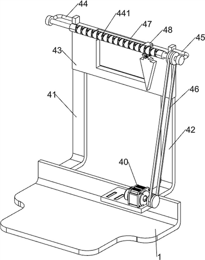
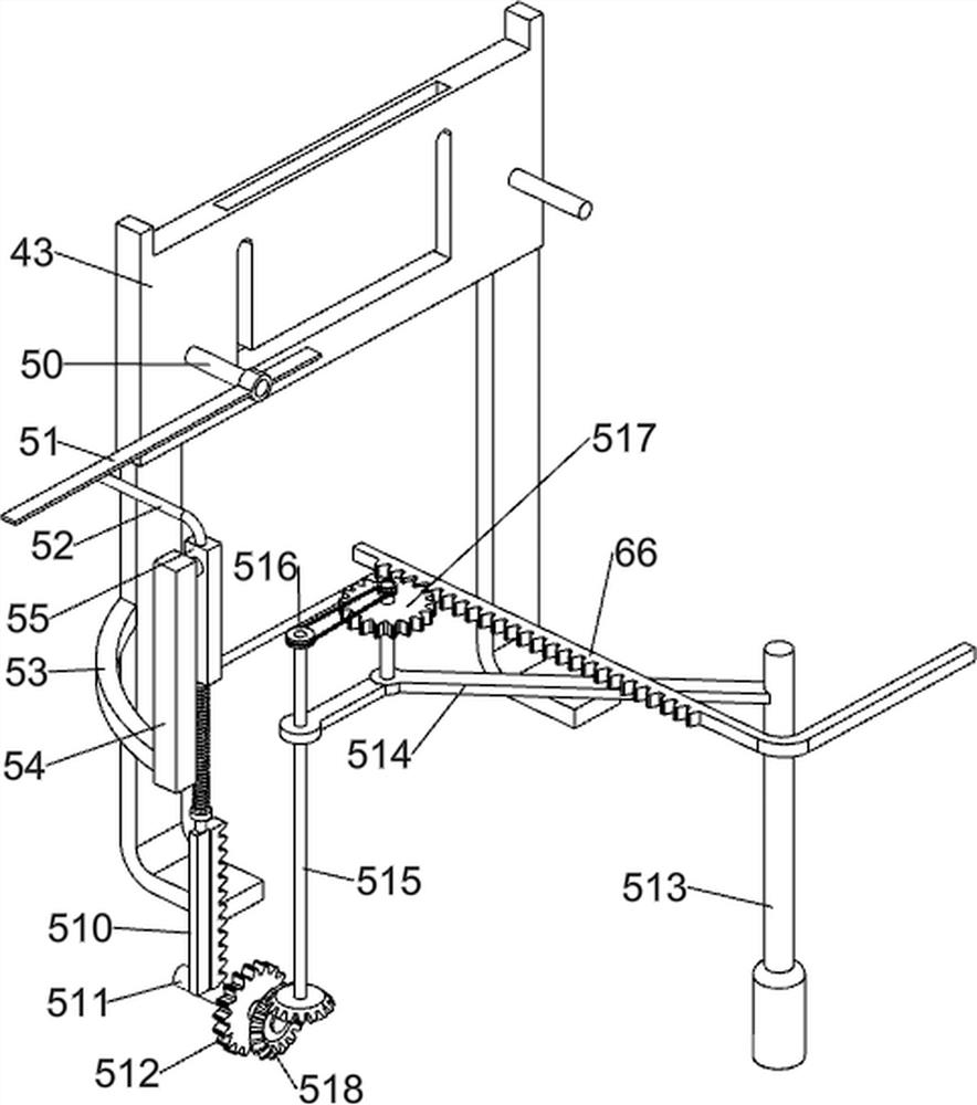
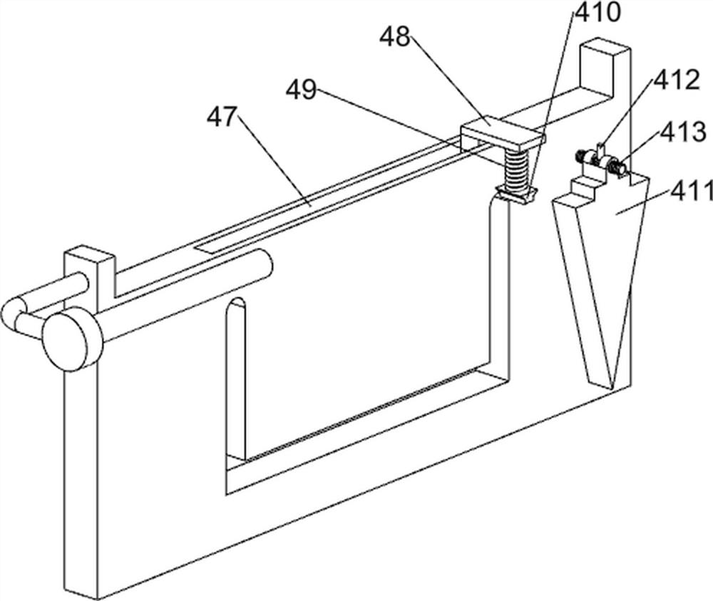
[0035] On the basis of Example 1, such as figure 1 , image 3 , Figure 4 , Figure 5 , Figure 6 , Figure 7 , Figure 8 and Figure 9 As shown, it also includes a moving mechanism 4, and the moving mechanism 4 includes a reduction box 40, a first support plate 41, a second support plate 42, a slide rail plate 43, a second bearing seat 44, a twist shaft 441, and a third bearing seat 45 , the first transmission assembly 46, the slider 48, the third spring 49, the connecting block 410, the wedge block 411, the T-shaped bar 412 and the torsion spring 413; The output shaft on the right side of 20 is connected, the left part of the rear side of the base plate 1 is provided with a first support plate 41, the rear right part of the base plate 1 is provided with a second support plate 42, and the second support plate 42 and the first support plate 41 are provided There is a slide rail plate 43, and the handle 30 is slidingly connected with the slide rail plate 43. The left sid...
PUM
 Abstract
Description
Claims
Application Information