Chamfering device for machining

A chamfering device and machining technology, used in grinding drive devices, metal processing equipment, grinding/polishing safety devices, etc., can solve the problems of hand injury and high labor intensity, reduce labor intensity and achieve good results , the effect of improving quality

Inactive Publication Date: 2021-03-02
王为
View PDF6 Cites 2 Cited by
  • Summary
  • Abstract
  • Description
  • Claims
  • Application Information

AI Technical Summary

Problems solved by technology

[0004] The object of the present invention is to provide a kind of chamfering device for mechanical processing, to solve the above-mentioned background technology, and in the prior art, manual hand-held mode is used to perform chamfering work on the grinder, which is labor-intensive and easy to cause hand damage Damaged technical issues

Method used


Image

  • Chamfering device for machining
  • Chamfering device for machining
  • Chamfering device for machining

Examples


Embodiment Construction

[0028] In order to make the object, technical solution and advantages of the present invention clearer, the present invention will be further described in detail below in conjunction with the accompanying drawings and embodiments. It should be understood that the specific embodiments described here are only used to explain the present invention, not to limit the present invention.

[0029] The components of the embodiments of the invention generally described and shown in the figures herein may be arranged and designed in a variety of different configurations. Accordingly, the following detailed description of the embodiments of the invention provided in the accompanying drawings is not intended to limit the scope of the claimed invention, but merely represents selected embodiments of the invention.

[0030] Based on the embodiments of the present invention, all other embodiments obtained by persons of ordinary skill in the art without making creative efforts belong to the pro...


PUM


Abstract

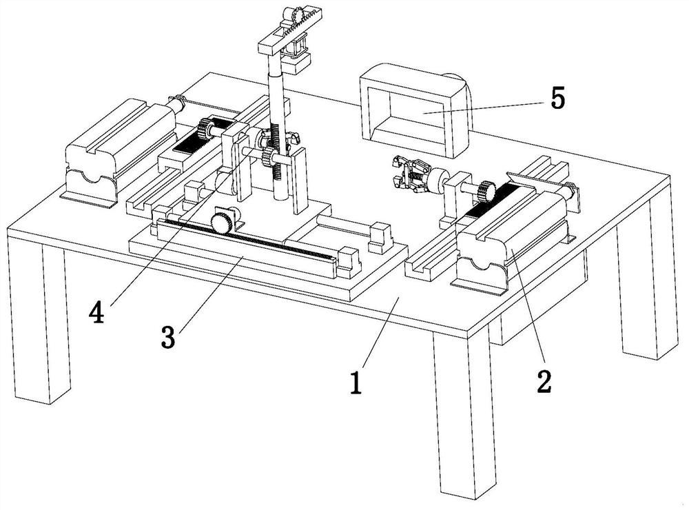
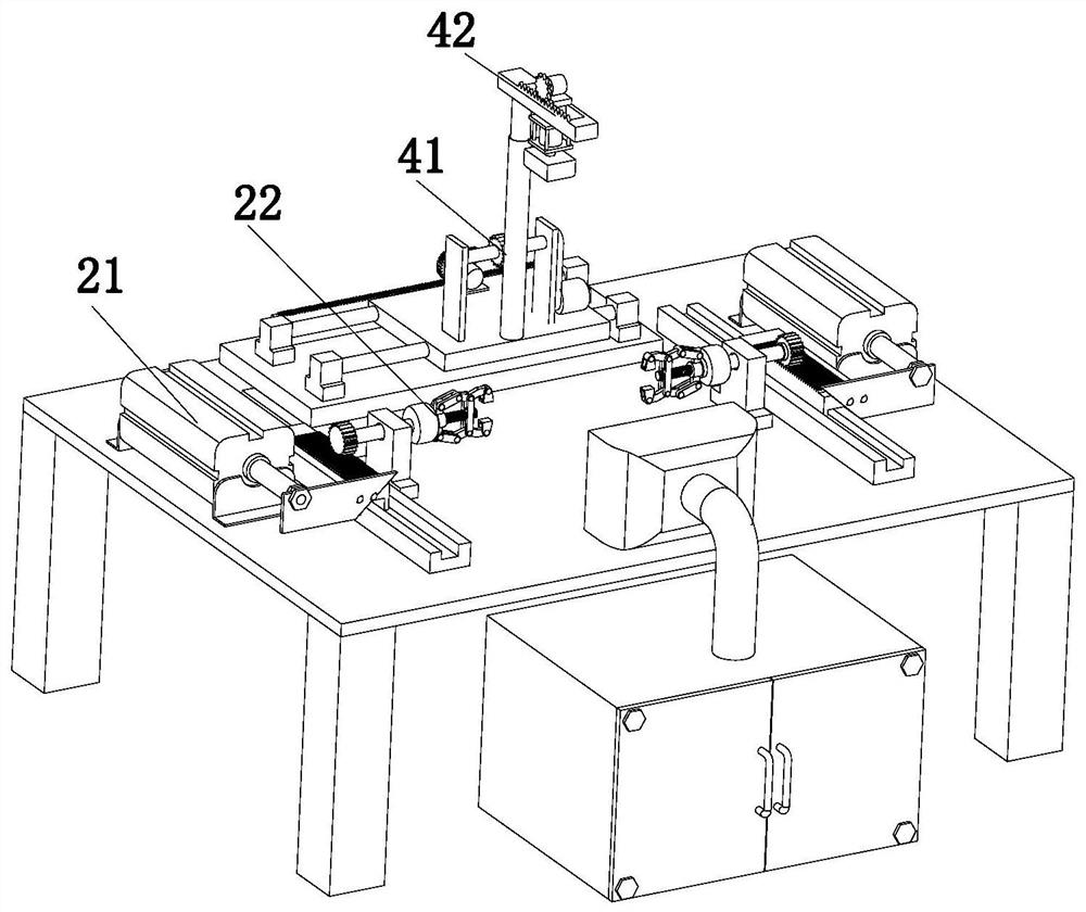
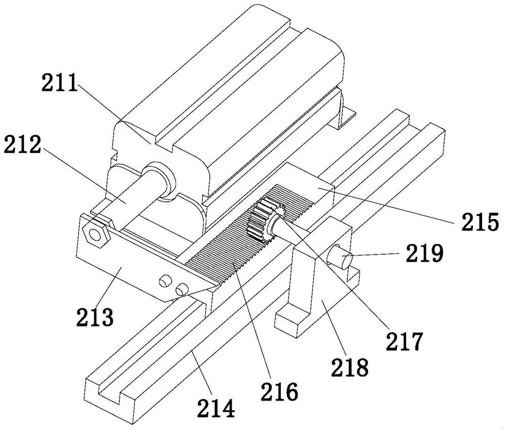
The invention discloses a chamfering device for machining, and relates to the technical field of machining. The chamfering device comprises a workbench, two groups of rotary fixing assemblies, a moving assembly, a chamfering assembly and a scrap removing assembly, wherein the two groups of rotary fixing assemblies are symmetrically arranged on the workbench, the moving assembly are fixedly arranged on one side of the workbench, the chamfering assembly is fixedly arranged at the working end of the moving assembly, and the scrap removing assembly is fixedly arranged on the other side of the workbench. According to the chamfering device, the working efficiency is greatly improved, the quality of chamfering operation is guaranteed, the labor intensity of workers is relieved, and the practicability of the device is greatly improved.

Description

technical field [0001] The invention relates to the technical field of machining, in particular to a chamfering device for machining. Background technique [0002] As we all know, chamfering refers to the processing of cutting the corners of parts into a certain slope. The purpose of chamfering is to remove the burrs produced by machining on the parts, and also to facilitate the assembly of parts, the chamfering is generally made at the end of the parts. Generally, the function of chamfering is to remove burrs and make it beautiful. However, the chamfers specified in the drawings are generally the requirements of the installation process, such as the installation guide of the bearing, and some circular arc chamfers (or called circular arc transitions) can also reduce stress concentration and strengthen shafts. The effect of the strength of the part. In addition, it can also make assembly easier, usually before the end of processing. [0003] On agricultural machinery part...

Claims


Application Information

Patent Timeline
Patent Type & Authority Applications(China)
IPC IPC(8): B24B9/00B24B41/06B24B47/00B24B47/16B24B47/20B24B55/06
CPCB24B9/00B24B41/06B24B47/20B24B47/16B24B47/00B24B55/06
Inventor 不公告发明人
Owner 王为
Why Eureka
Try Eureka