Power distribution system

A technology of distribution system and power, applied in the field of power distribution system, can solve the problems of inconvenient maintenance and complex structure, and achieve the effect of avoiding potential safety hazards, compact overall structure and prolonging service life.

Active Publication Date: 2021-03-02
GUOCHUANG INNOVATION CENTER OF MOBILE ENERGY (JIANGSU) CO.,LTD.
View PDF6 Cites 0 Cited by
  • Summary
  • Abstract
  • Description
  • Claims
  • Application Information

AI Technical Summary

Problems solved by technology

[0005] In order to solve the technical problem that each connector corresponds to a drive device and multiple guide rails in the power distribution system of the prior art, the structure is complicated and maintenance is inconvenient, and a power distribution system is proposed. One drive module corresponds to multiple connections device, making the power distribution system more compact, cost-effective, and easy to maintain

Method used


Image

  • Power distribution system
  • Power distribution system
  • Power distribution system

Examples


Embodiment 1

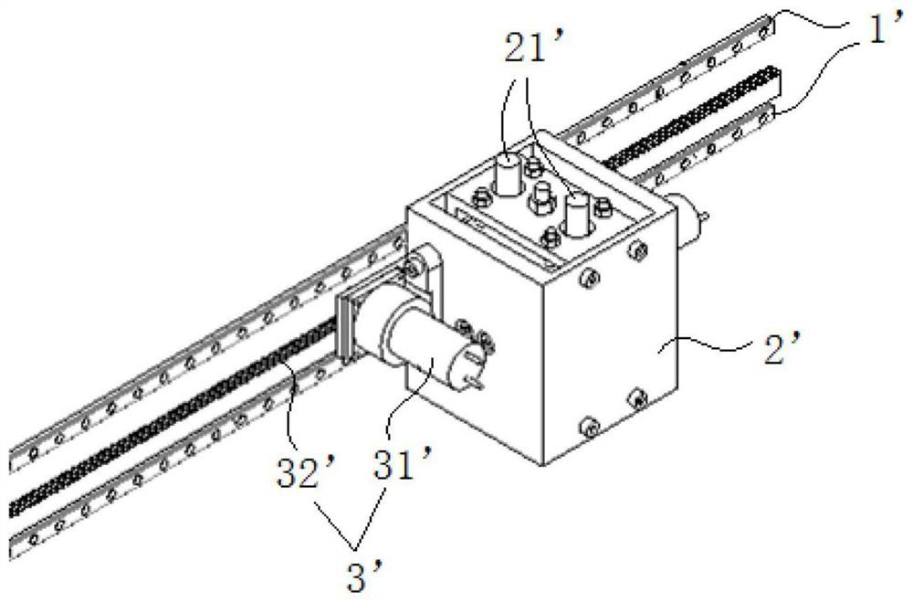
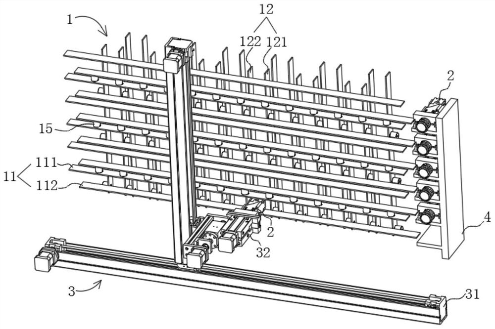
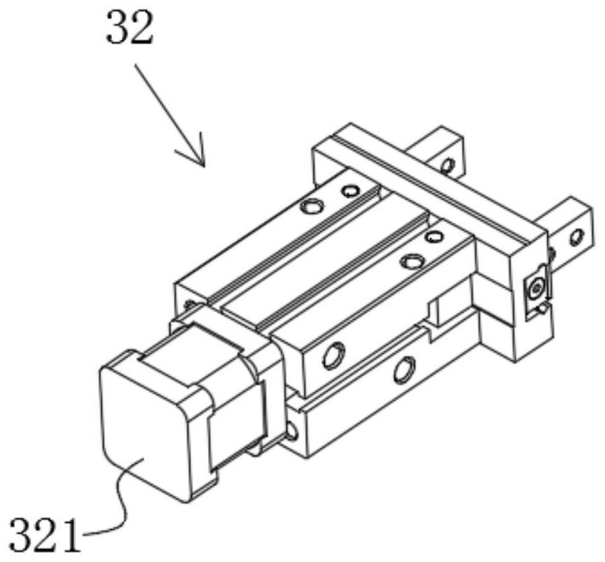
[0063] Such as Figure 2-3 As shown, this embodiment provides a power distribution system, the power distribution system includes a copper bar assembly 1, a plurality of connectors 2 and a moving assembly 3, the copper bar assembly 1 includes multiple sets of input copper bars 11 and multiple sets of output copper bars 12. The output copper bar 12 is arranged on one side of the input copper bar 11, a plurality of connectors 2 are arranged on the side of the copper bar assembly 1, and the moving assembly 3 includes a gripper 32 and a driving module 31 for driving the gripper 32 to move , specifically, the input copper bars 11 of this embodiment are connected to the charging power source, and the output copper bars 12 are connected to the charging terminals. Every two sets of input copper bars 11 are separated by insulators 15, and every two sets of output copper bars 12 are separated. Separated by insulators 15, further, a bracket 4 is arranged on the side of the copper bar ass...

Embodiment 2

[0083] Such as Figure 15-16 As shown, the difference between the power distribution system of the present embodiment and the first embodiment is that the linkage mechanism in the connector 2 of the present embodiment and each limit member on the limit seat 27 are different from the first embodiment. The link mechanism of the present embodiment includes two push rods 221, the first end of the push rod 221 is configured with an electrode, and the second end of the push rod 221 is hinged to the drive rod 24. Further, the link mechanism of this embodiment also includes two link rods 222, two connecting rods 222 and two push rods 221 form a hinge four-bar mechanism, the first end of the connecting rod 222 is hinged with the first end of the corresponding push rod 221, and the second end of the connecting rod 222 is configured as a fixed At the hinged end, the driving member 321 drives the push rod 221 in each linkage mechanism to move by means of the driving rod 24 .

[0084] Fur...

Embodiment 3

[0087] Such as Figure 19 As shown, the difference between the power distribution system of this embodiment and Embodiment 1 or 2 is that this embodiment also has multiple sets of parallel copper bars 13 corresponding to the output copper bars 12 on one side of the output copper bars 12, The parallel copper bars 13 are electrically connected to the output copper bars 12 in one-to-one correspondence through conductive elements 14 . Specifically, the output copper bar 12 is arranged on one side of the input copper bar 11, and the parallel copper bar 13 is arranged on one side of the output copper bar 12, and the parallel copper bar 13 and the output copper bar 12 pass through the conductive member in one-to-one correspondence 14 connection, the conductive part 14 can be a copper bar or a wire, so, as Figure 20 As shown, a set of mobile components 3, brackets 4 and multiple connectors 2 can be arranged on one side of the parallel copper bars 13, and a set of output copper bars ...


PUM


Abstract

The invention relates to the technical field of charging, in particular to a power distribution system, which comprises a copper bar assembly, a plurality of connectors and a moving assembly, and is characterized in that the copper bar assembly comprises a plurality of groups of input copper bars and a plurality of groups of output copper bars, the output copper bars are arranged on one sides of the input copper bars, and the connectors are arranged on the sides of the copper bar assembly; the moving assembly comprises a clamping jaw and a driving module for driving the clamping jaw to move, when the clamping jaw grabs the connector to move to a designated position, the connector is inserted into the copper bar assembly, and electrodes on the connector are electrically connected with the input copper bars and the corresponding output copper bars. Compared with the prior art, the power distribution system is more compact in structure, low in cost, convenient to maintain and high in expansibility.

Description

technical field [0001] The invention relates to the technical field of charging, in particular to a power distribution system. Background technique [0002] At present, electric vehicles are attracting more and more attention, and the charging of electric vehicles is related to the popularization and promotion of electric vehicles. In order to charge electric vehicles with different capacities, many companies are currently researching and manufacturing power distribution systems that can perform power distribution. . [0003] Existing power distribution systems generally use a single relay / contactor to form an MxN array, or use multiple fixed multi-contact relays / contactors, which are essentially an array of MxN relay groups. . The disadvantage of directly using the relay array is that the amount of relays is large, the cost is high, and MxN complex control circuits are required. This kind of solution is quite complicated in terms of structure, electricity, hardware, and s...

Claims


Application Information

Patent Timeline
Patent Type & Authority Applications(China)
IPC IPC(8): B60L53/16B60L53/35H01R13/627H01R13/62H01R11/01
CPCB60L53/16B60L53/35H01R13/627H01R13/62H01R11/01Y02T90/167
Inventor 袁江徽朱君亮张程飞何青李德胜郑隽一张育铭
Owner GUOCHUANG INNOVATION CENTER OF MOBILE ENERGY (JIANGSU) CO.,LTD.
Why Eureka
Try Eureka