
Railway hopper car discharging device and railway hopper car

A technology of unloading device and hopper car, applied in the direction of hopper car, railway car body parts, transportation passenger car, etc. Control flexible and simple effects

Pending Publication Date: 2021-03-02
CRRC TAIYUAN CO LTD
View PDF0 Cites 1 Cited by
  • Summary
  • Abstract
  • Description
  • Claims
  • Application Information

AI Technical Summary

Problems solved by technology

[0003] Unloading to both sides of the track is suitable for the application environment where the unloading area is set on both sides of the track, and the bottom doors on both sides must be opened at least once to complete the unloading task, otherwise there is aggregate on one side of the car body and it cannot be unloaded cleanly
The single-side unloading type can complete the unloading of the whole vehicle by opening the bottom door on any side, but the height of the center of gravity of the vehicle is difficult to control, the design is difficult, and it does not match the actual needs and comprehensive benefits of the unloading site in my country
The horizontal door hopper car that unloads to the inner side of the track cannot integrate the function of unloading to both sides of the track
In practice, none of the hopper cars in use can integrate the two functions of unloading on both sides and the middle of the track at the same time or realize the flexible switching of the two methods, which greatly reduces the versatility of the vehicle

Method used


Image

  • Railway hopper car discharging device and railway hopper car
  • Railway hopper car discharging device and railway hopper car
  • Railway hopper car discharging device and railway hopper car

Examples


Embodiment 1

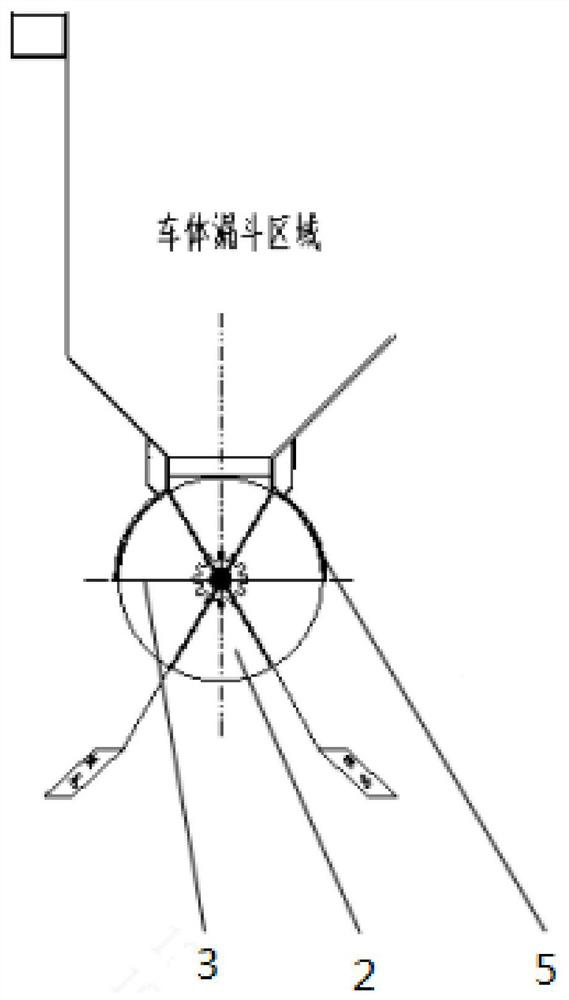
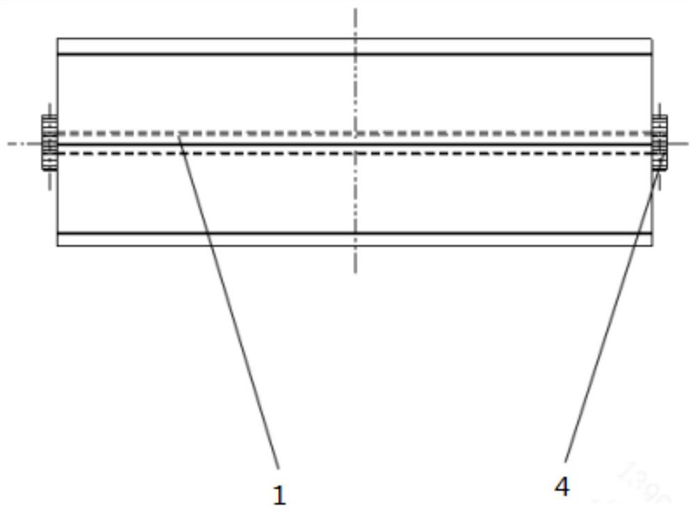
[0073] Such as Figure 1 to Figure 3 Shown, a kind of railway hopper car unloading device comprises:

[0074] The central tube 1 is arranged below the discharge port of the railway hopper car;

[0075] Two baffles 2 are respectively arranged at both ends of the central cylinder 1;

[0076] A plurality of partitions 3 are arranged on the outer periphery of the central cylinder 1 along the radial direction of the central cylinder 1, and the two ends of the partitions 3 are respectively connected with the two baffles 2, so that two adjacent partitions 3 and two The baffle plate 2 forms a collecting tank with an open top;

[0077] The transmission structure 4 is arranged on at least one end of the central cylinder 1, and the transmission mechanism is used to cooperate with the driving mechanism.

[0078] In this embodiment, the baffle 2 is disc-shaped.

[0079] In this embodiment, arc-shaped outer baffles 5 are arranged symmetrically on both sides of the discharge port, and th...

Embodiment 2

[0092] Such as Figure 4 As shown, the difference between the railway hopper car unloading device in the present embodiment and the railway hopper car unloading device in Embodiment 1 is:

[0093] In this embodiment, a cover plate 6 is provided on the top of the collecting tank, and the cover plates 6 are arranged on the collecting tank at intervals, so that one of the two adjacent collecting tanks is open and the other is closed.

[0094] In this embodiment, the cover plate 6 is in the shape of an arc, and the cover plate 6 matches the circumferential curve of the baffle plate 2 .

[0095] Specifically, the cover plate 6 is fixed on the top of the collecting tank, and the adjacent collecting tank of the collecting tank containing the material is closed by the cover plate 6. When the collecting tank rotates around the central cylinder 1, the adjacent collecting tank The groove seals the discharge port by the cover plate 6, which can also prevent material leakage and splashing...


PUM


Abstract

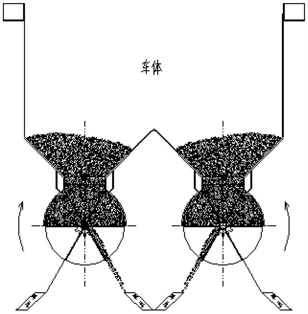
The invention discloses a railway hopper car discharging device and a railway hopper car, and relates to the technical field of discharging devices. The railway hopper car discharging device comprisesa center cylinder arranged below a discharging port of the railway hopper car, two baffles arranged at the two ends of the center cylinder correspondingly, and a plurality of partition plates arranged on the periphery of the center cylinder in the radial direction of the center cylinder. The two ends of each partition plate are connected with the two baffles respectively, so that the two adjacentpartition plates and the two baffles form a material collecting groove with the open top, the transmission structure is arranged at at least one end of the center cylinder, the transmission mechanismis used for being matched with a driving mechanism, and the discharging device transmits power of the driving mechanism through the transmission mechanism to enable the center cylinder to drive the material collecting groove to rotate. Materials are dumped by rotating the material collecting groove around the center cylinder, so that the discharging device achieves the purpose of discharging towards the two sides or the inner side by changing the rotating direction of the center cylinder, the discharging device is flexible and simple to control, and the discharging amount and the dischargingflow are controlled more visually and conveniently.

Description

technical field [0001] The invention belongs to the technical field of unloading devices, and more specifically relates to a railway hopper car unloading device and a railway hopper car. Background technique [0002] At present, the domestic railway hopper car unloading types mainly include: unloading on both sides or one side of the track and unloading along the track to the inner side of the track. The car body structures of the two unloading methods are quite different. [0003] Unloading to both sides of the track is suitable for the application environment where the unloading area is set on both sides of the track, and the bottom doors on both sides must be opened at least once to complete the unloading task, otherwise there is aggregate on one side of the car body and it cannot be unloaded cleanly . The single-side unloading type can complete the unloading of the whole vehicle by opening the bottom door on any side, but the height of the center of gravity of the vehic...

Claims


Application Information

Patent Timeline
IPC IPC(8): B61D7/02B61D7/32B61D7/24
CPCB61D7/02B61D7/32B61D7/24
Inventor 冯凯李鹏张燕袁太红李旭英赵祖兴刘文胜谢剑锋张洁
Owner CRRC TAIYUAN CO LTD
Learn More