
Automobile body front structure and automobile

A technology for the front part of the car body and supporting structure, which is applied to the substructure, vehicle parts, transportation and packaging, etc., and can solve the problems of small frontal overlap, poor impact resistance of the car body, easy to pull the front longitudinal beam, etc., and achieve reduction Deformation amount, enhanced impact resistance, and improved safety effects

Active Publication Date: 2021-03-02
CHERY AUTOMOBILE CO LTD
View PDF6 Cites 2 Cited by
  • Summary
  • Abstract
  • Description
  • Claims
  • Application Information

AI Technical Summary

Problems solved by technology

[0002] The 25% small offset collision has attracted more and more attention. In this type of collision, the frontal overlap between the obstacle and the vehicle body is small, and the coverage is only 25%, which can only cover the front wheelhouse area outside the front longitudinal beam, resulting in The longitudinal beam does not participate in the collision, and the front longitudinal beam cannot absorb the collision energy, which makes the impact resistance of the body poor
[0004] However, when the vehicle body structure in the related art responds to a 25% small offset collision, since the connecting piece is connected to the outer side wall of the front longitudinal beam, when the collision impact is received, the outer side wall connected to the connecting piece on the front side beam is partially The force is large, so it is easy to pull the front longitudinal beam, resulting in bending of the front longitudinal beam, and then making the force transmission of the front longitudinal beam invalid

Method used


Image

  • Automobile body front structure and automobile
  • Automobile body front structure and automobile
  • Automobile body front structure and automobile

Examples


Embodiment Construction

[0031] In order to make the purpose, technical solution and advantages of the present disclosure clearer, the implementation manners of the present disclosure will be further described in detail below in conjunction with the accompanying drawings.

[0032] Unless otherwise defined, the technical terms or scientific terms used herein shall have the usual meanings understood by those having ordinary skill in the art to which the present disclosure belongs. "First", "second", "third" and similar words used in the specification and claims of this disclosure do not indicate any order, quantity or importance, but are only used to distinguish different components . Likewise, words like "a" or "one" do not denote a limitation in quantity, but indicate that there is at least one. Words such as "comprises" or "comprising" and similar terms mean that the elements or items listed before "comprising" or "comprising" include the elements or items listed after "comprising" or "comprising" a...


PUM


Abstract

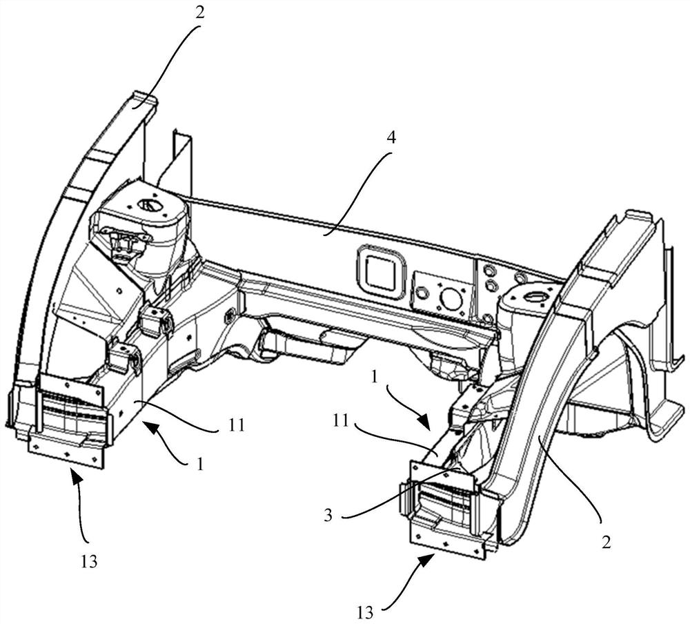
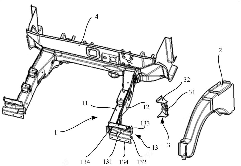
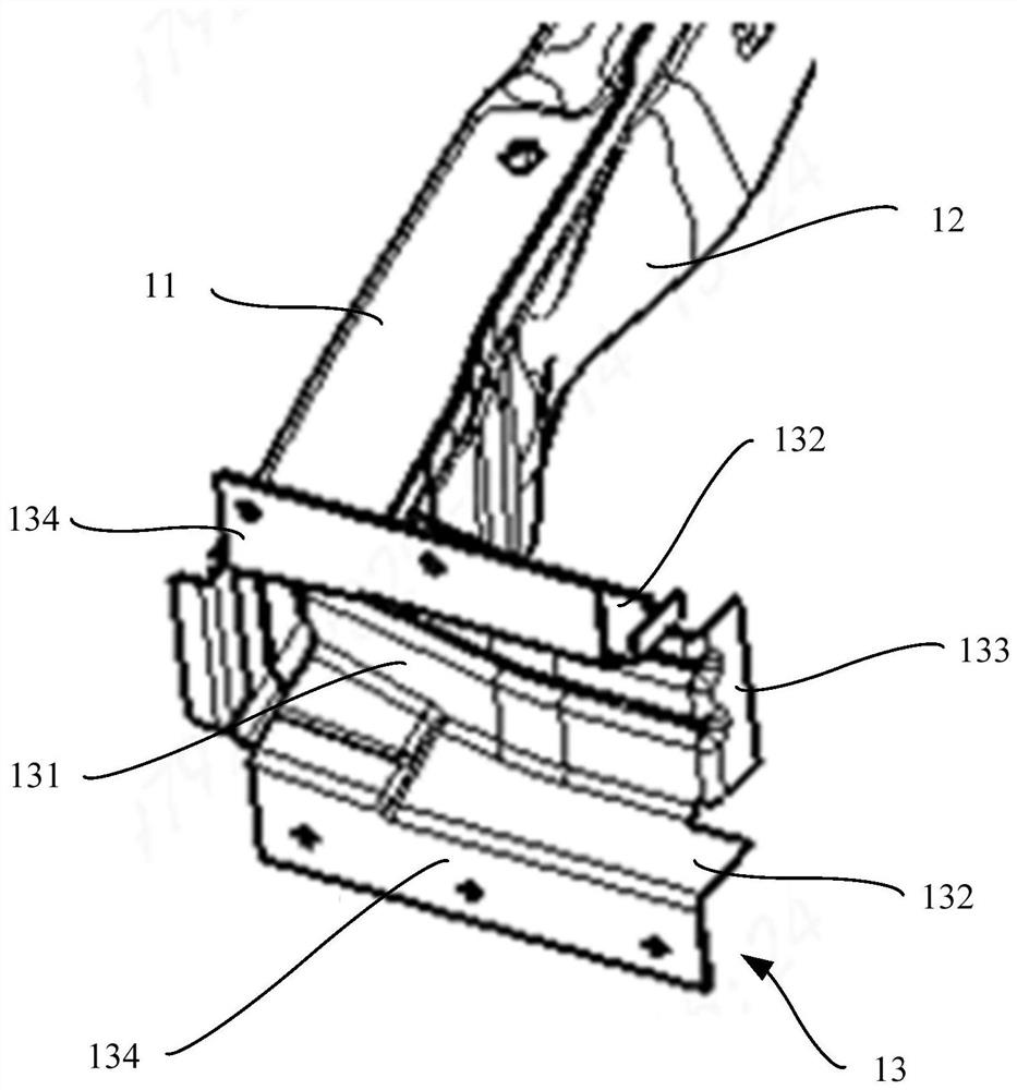
The present invention provides an automobile body front structure which comprises a front longitudinal beam assembly and a front wheel cover side reinforcing beam. The front longitudinal beam assemblycomprises a front longitudinal beam inner plate, a front longitudinal beam cover plate and a front longitudinal beam supporting plate, wherein the front longitudinal beam inner plate comprises a longitudinal beam bottom plate and two longitudinal beam side plates located on the opposite two sides of the longitudinal beam bottom plate; the two longitudinal beam side plates are connected with the front longitudinal beam cover plate, and the front longitudinal beam cover plate is opposite to the longitudinal beam bottom plate; parts of the front longitudinal beam supporting plate is located in agroove defined by the longitudinal beam bottom plate and the longitudinal beam side plates; the part, located in the groove, of the front longitudinal beam supporting plate is connected with the longitudinal beam bottom plate and the longitudinal beam side plates; the plate face of the front longitudinal beam supporting plate is connected with the side edges of the front longitudinal beam cover plate; and the front wheel cover side reinforcing beam is connected with the part, located outside the groove, of the front longitudinal beam supporting plate. The energy absorption effect of the automobile body front structure can be improved, and the deformation amount of the passenger compartment is reduced.

Description

technical field [0001] The present disclosure relates to the technical field of automobiles, in particular to a vehicle body front structure and an automobile. Background technique [0002] The 25% small offset collision has attracted more and more attention. In this type of collision, the frontal overlap between the obstacle and the vehicle body is small, and the coverage is only 25%, which can only cover the front wheelhouse area outside the front longitudinal beam, resulting in The longitudinal beams are not involved in the collision, and the front longitudinal beams cannot absorb the collision energy, which makes the impact resistance of the vehicle body poor. [0003] In the related art, the solution to deal with 25% small offset collision is mainly to add connectors on the side wall of the front longitudinal beam, and connect the front wheel house side reinforcement beam to the connectors, so as to strengthen the front wheel house side through the connectors. The impa...

Claims


Application Information

Patent Timeline
Patent Type & Authority Applications(China)
IPC IPC(8): B62D21/15
CPCB62D21/155B62D25/08B62D25/082B62D21/152B62D27/023
Inventor 杜士威李程常信平袁堂福
Owner CHERY AUTOMOBILE CO LTD
Learn More