

Beam structure vibration fatigue device
A vibration fatigue and beam structure technology, applied in the field of fatigue testing machines, can solve the problems of inability to implement equipment, inability to easily change the restraint mode, etc., and achieve the effect of small distortion
- Summary
- Abstract
- Description
- Claims
- Application Information
AI Technical Summary
Problems solved by technology
Method used
Image

Examples
Embodiment 1
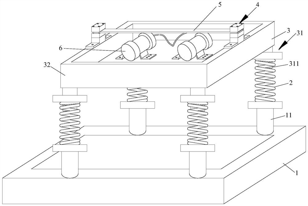
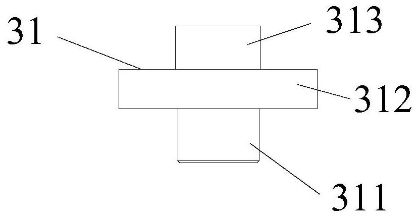
[0042] from figure 1 It can be seen that the beam structure vibration fatigue device shown in the first embodiment includes a base 1, a support column 11, a vibration isolation spring 2, a vibration platform 3, a support joint 31, a beam end clamping seat 4, a beam specimen 5, a vibration motor6. Four T-shaped support columns 11 are welded on the four corners of the base 1, the vibration isolation spring 2 is a metal helical column compression spring, the support column 11 is welded to the bottom coil of the vibration isolation spring 2, and the top coil of the vibration isolation spring 2 is The support joint 31 is welded. recombine as figure 2 It can be seen that the support joint 31 includes three parts, the middle is a disc 312, and the two ends are respectively a spring guide post 311 and a support column 313. The top coil of the support spring 2 passes through the spring guide post 311 and is welded on the bottom surface of the disc 312. The top surface of the suppor...
Embodiment 2
[0051] Such as Figure 8 As shown, the difference between the second example and the first example lies in the structural shape and clamping method of the beam test piece, and the additional counterweight 7 . combine Figure 9 It can be seen that the top and bottom surfaces of one end of the beam specimen are planes, and the top and bottom surfaces of the other end are also planes. recombine Figure 10, a central through hole 52 is opened at the middle position of the beam test piece 5 . In order to increase the inertial excitation force, a counterweight 7 is installed on the beam specimen. The counterweight includes an upper counterweight 71 and a lower counterweight 72. The upper counterweight 71 and the lower counterweight 72 have the same structural shape and size. Both the counterweight 71 and the lower counterweight 72 have five through holes, among which four are at the four corners and one is at the middle. The upper counterweight 71 is installed above the beam tes...
Embodiment 3
[0054] The difference between the third example and the first example lies in the structural shape and clamping mode of the beam specimen. Such as Figure 11 with Figure 12 As shown, the top and bottom surfaces of both ends of the beam specimen are provided with arc-shaped grooves 51 . The two ends of the beam test piece are respectively installed on two rotatable clamping seats 41 at the ends of the beam. The structure and shape of the rotatable clamping seat 41 at the beam end in this embodiment is the same as that of the rotatable clamping seat at the beam end in Embodiment 1, and will not be repeated here. In this way, the beam specimen can rotate slightly at both ends of the beam specimen and move slightly in the horizontal direction, which is similar to the constraints of a simply supported beam structure. Simply supported beam structure is more common in engineering, such as bridge crane girder as simply supported beam structure. Based on the similarity theory, the...
PUM
 Abstract
Description
Claims
Application Information