

Positive bias high-end current detection circuit and electrical equipment applying same
A current detection circuit, positive bias technology, applied in the direction of measuring current/voltage, measuring only current, instruments, etc., can solve the problems of neglecting application innovation and improvement, high development process cost, low sampling resolution, etc., to avoid uncertainty performance, improve product reliability, and reduce the effect of sampling current distortion
- Summary
- Abstract
- Description
- Claims
- Application Information
AI Technical Summary
Problems solved by technology
Method used
Image

Examples
Embodiment 1
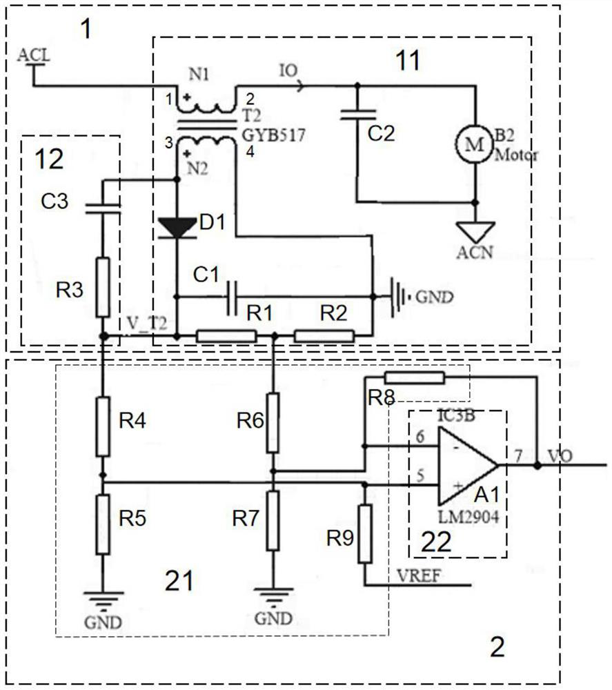
[0024] An embodiment of the present invention provides a positive bias high-end current detection circuit, such as figure 1 As shown, it includes a current transformer sampling module 1 for isolating and sampling the high-side current and a positive bias detection module 2 for positively biasing the high-side current sampled by the current transformer sampling module 1 to output, the current transformer The sampling module 1 is electrically connected to the positive bias detection module 2 .
[0025] In this way, the high-end current is isolated and sampled by the current transformer sampling module 1, and the positive bias output of the high-side current sampled by the current transformer sampling module 1 is detected by the positive bias detection module 2, thereby abandoning the single-resistor low-side sampling current method and avoiding the Ground potential fluctuations lead to inaccurate sampling, reduce sampling current distortion and avoid output uncertainty when the ...
Embodiment 2
[0044] Embodiment 2 of the present invention provides an electrical device, which includes the positive bias high-end current detection circuit.
[0045] Among them, the electrical equipment is high-power electrical equipment such as range hoods and steam ovens.
[0046] In the electrical equipment of the present invention, the high-end current is isolated and sampled by the current transformer sampling module, and the positive bias output of the high-end current sampled by the current transformer sampling module is detected by the positive bias detection module, thereby abandoning the single-resistor low-side sampling current mode and avoiding Inaccurate sampling due to ground potential fluctuations, reducing sampling current distortion and avoiding output uncertainty when the load is zero, low cost, high accuracy, and improved product reliability.
PUM
| Property | Measurement | Unit |
|---|---|---|
| Resistance | aaaaa | aaaaa |
| Resistance | aaaaa | aaaaa |
Abstract
Description
Claims
Application Information