
Optical receiving chip

A light receiving and chip technology, applied in the directions of light guides, optics, optical components, etc., can solve the problems of different polarization states, different group refractive indices, different optical signal delays, etc.

Active Publication Date: 2021-03-02
WUHAN OPTICAL VALLEY INFORMATION OPTOELECTRONICS INNOVATION CENT CO LTD
View PDF14 Cites 0 Cited by
  • Summary
  • Abstract
  • Description
  • Claims
  • Application Information

AI Technical Summary

Problems solved by technology

[0002] In the prior art, the optical signal is transmitted to the photodetector of the optical receiving chip through the waveguide in the optical receiving chip, and the photodetector converts the incident optical signal into an electrical signal. The usual problems of the optical receiving chip in the prior art are Since the received optical signals have different polarization states, the group refractive index of light with different polarization states in the same waveguide is often different, that is, the time delay of optical signals with different polarization states is different, resulting in signal distortion

Method used


Image

  • Optical receiving chip
  • Optical receiving chip
  • Optical receiving chip

Examples


Embodiment Construction

[0024] It should be noted that, in the case of no conflict, the embodiments in the application and the technical features in the embodiments can be combined with each other. Undue Limitation of This Application. The present application will be further described in detail below in conjunction with the accompanying drawings and specific embodiments.

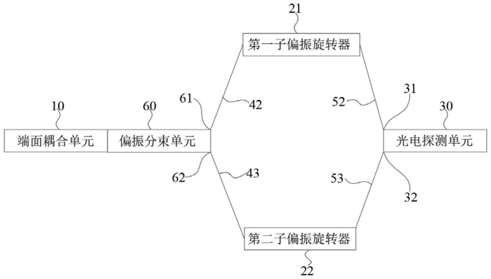
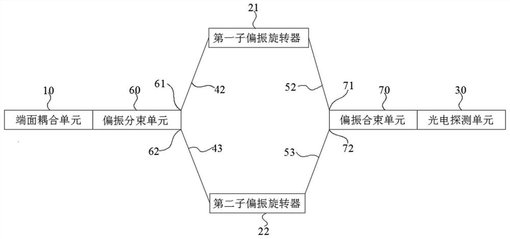
[0025] See Figure 1 ~ Figure 3 , the embodiment of the present application provides a light receiving chip, the light receiving chip includes an input coupling unit 10, a polarization rotation unit 20, a photodetection unit 30, a first transmission waveguide 40, and a second transmission waveguide 50, the input coupling unit 10 is used for Receive an optical signal, the optical signal has input TE polarized light and / or input TM polarized light; the polarization rotation unit 20 can convert the input TE polarized light by 90 degrees into output TM polarized light, and can convert the input TM polarized light by 90 degrees To out...


PUM


Abstract

The invention provides an optical receiving chip. The optical receiving chip comprises an input coupling unit, a polarization rotation unit, a photoelectric detection unit, a first transmission waveguide and a second transmission waveguide; an optical signal has input TE polarized light and / or input TM polarized light; the polarization rotation unit can rotate the input TE polarized light by 90 degrees to convert the input TE polarized light into output TM polarized light, and can rotate the input TM polarized light by 90 degrees to convert the input TM polarized light into output TE polarizedlight; the first transmission waveguide is used for transmitting the input TE polarized light and / or the input TM polarized light from the input coupling unit to the polarization rotation unit; the second transmission waveguide is used for transmitting the output TE polarized light and / or the output TM polarized light from the polarization rotation unit to the photoelectric detection unit; and the total length of the first transmission waveguide is equal to the total length of the second transmission waveguide. The optical receiving chip provided by the invention can realize polarization-independent optical signal receiving.

Description

technical field [0001] The present application relates to the technical field of semiconductor integration, in particular to a light receiving chip. Background technique [0002] In the prior art, the optical signal is transmitted to the photodetector of the optical receiving chip through the waveguide in the optical receiving chip, and the photodetector converts the incident optical signal into an electrical signal. The usual problems of the optical receiving chip in the prior art are Since the received optical signals have different polarization states, the group refractive index of light with different polarization states in the same waveguide is often different, that is, the time delay of optical signals with different polarization states is different, resulting in signal distortion. Contents of the invention [0003] In view of this, the embodiment of the present application expects to provide a light receiving chip that can avoid the problem of signal distortion due ...

Claims


Application Information

Patent Timeline
IPC IPC(8): G02B6/126G02B6/122G02B6/26G02B27/28
CPCG02B6/126G02B6/122G02B6/26G02B27/286G02B27/283
Inventor 陈代高肖希王磊刘敏胡晓张宇光余少华
Owner WUHAN OPTICAL VALLEY INFORMATION OPTOELECTRONICS INNOVATION CENT CO LTD
Learn More