Clock movement provided with positioning device

A technology for a clock movement and a positioning device, which is applied in the field of clocks and can solve problems such as high requirements and energy loss

Active Publication Date: 2021-03-02
SHENZHEN PRECISION CHRONOMETER TECH CO LTD
View PDF18 Cites 0 Cited by
  • Summary
  • Abstract
  • Description
  • Claims
  • Application Information

AI Technical Summary

Problems solved by technology

[0004] In view of the above-mentioned related technologies, there are the following defects: when the dial dial dials the calendar wheel, in addition to providing the driving force to push the calendar wheel to overcome the frictional force and rotate, it is also necessary to provide the teeth on the calendar ring to push the calendar positioning rod away. thrust, which will require a very high torque through the mechanism of the small and medium-sized shaft core, which has high requirements on the movement, and the friction of the date ring in the watch also brings energy loss

Method used


Image

  • Clock movement provided with positioning device
  • Clock movement provided with positioning device
  • Clock movement provided with positioning device

Examples


Embodiment Construction

[0033] The following is attached Figure 1-5 The application is described in further detail.

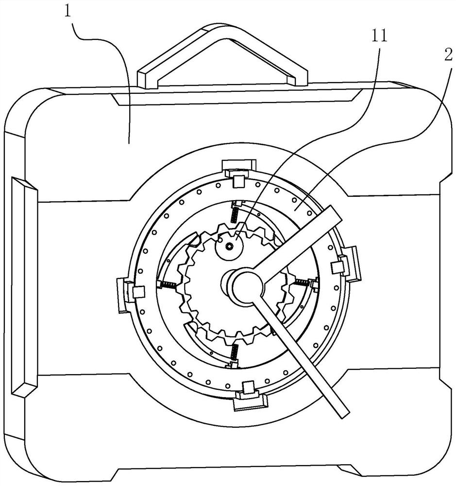
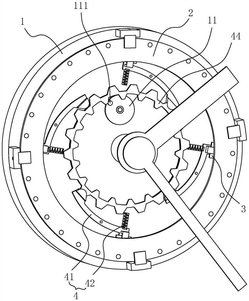
[0034] The embodiment of the application discloses a watch movement provided with a positioning device. refer to figure 1 The watch movement includes a movement base 1, a date dial 11 and a calendar wheel 2, the date dial 11 is rotatably mounted on the top wall of the movement base 1, and the date dial 11 passes through the hour hand movement on the movement base 1. Gear drive connection.

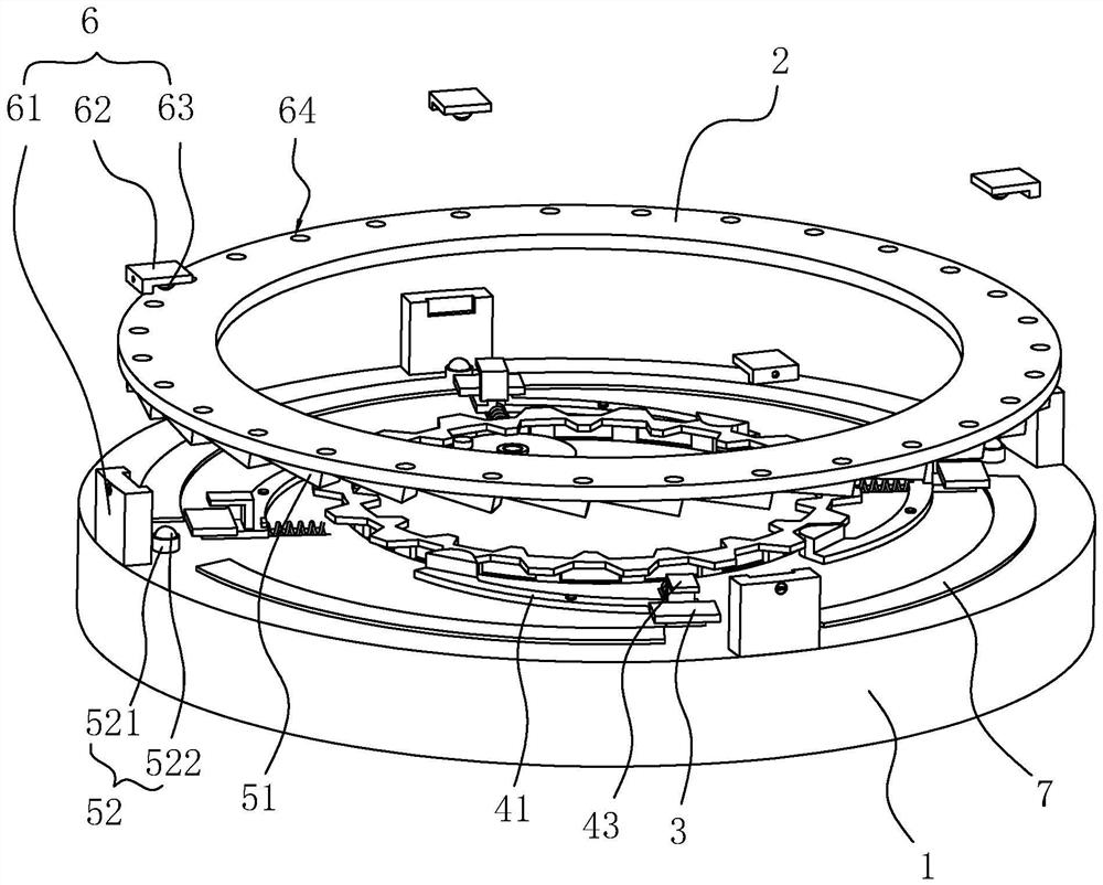
[0035] refer to figure 2 , 3 The top wall of the core base 1 is vertically integrally formed with a support rod 61 close to the edge, and the top of the support rod 61 is detachably connected to the top plate 62 on the side close to the center line of the core base 1 through bolts. The support rod 61 and the top plate 62 There are multiple sets of movement base 1 at intervals along the circumference of the calendar wheel 2 , and in this embodiment, there are four sets of support rods 61 and ...


PUM


Abstract

The invention relates to a clock movement provided with a positioning device. The movement comprises a movement seat, a date dial wheel and a calendar wheel, the date dial wheel is rotatably arrangedon the movement seat, the calendar wheel is coaxially and movably arranged above the movement seat, the calendar wheel is magnetic, and a magnetic sheet is arranged between the movement seat and the calendar wheel. A driving mechanism used for driving the magnetic sheet to move back and forth is arranged on the movement seat, a pushing mechanism used for driving the calendar wheel to step in one direction when the calendar wheel falls down is arranged on the movement seat, and a positioning mechanism used for positioning the calendar wheel is arranged on the movement seat. In the rotating process of a hour hand movement, the date dial wheel rotates for a circle, the magnetic sheet is sequentially driven to leave from the magnetic field below the calendar wheel and then enter, the calendarwheel falls under the action of gravity and is driven to step by one grid in a character moving direction of a disc surface, and after the magnetic sheet enters the magnetic field again, the calendarwheel rises and is limited to rotate, and character moving work of the calendar wheel is completed. A torque force applied to the movement is reduced, and the service life of the movement is prolonged.

Description

technical field [0001] The present application relates to the field of watch technology, in particular to a watch movement provided with a positioning device. Background technique [0002] Radio-wave clocks are the fifth generation of timekeepers in the development of human timing technology, after hourglasses, sundials, mechanical clocks, and quartz clocks. The emergence of radio-wave clock technology and products is another revolution in the history of human timing. Typically, a disc or ring used to display calendar data (date, week, month, etc.) is held in any one of a number of display positions by jumpers (also known as jump springs). [0003] The patent with the authorized announcement number CN2470857Y discloses a watch calendar instantaneous jump mechanism, which includes an hour wheel, a double-linked overwheel, a date dial, a calendar head, a calendar ring, and a calendar positioning rod. slot, and a cam fixedly connected to the calendar dial head is looped on the...

Claims


Application Information

Patent Timeline
Patent Type & Authority Applications(China)
IPC IPC(8): G04B19/253
CPCG04B19/25306
Inventor 赵希雷李德力刘何王涛赵祺乐
Owner SHENZHEN PRECISION CHRONOMETER TECH CO LTD
Why Eureka
Try Eureka