

Intelligent electronic lock based on trusted identification technology
An electronic lock and intelligent technology, which is applied in the field of trusted identification technology and the Internet of Things, can solve problems such as empty locks and false locks that cannot be solved by the lock head jumping over the locked object
- Summary
- Abstract
- Description
- Claims
- Application Information
AI Technical Summary
Problems solved by technology
Method used
Image


Examples
Embodiment 1
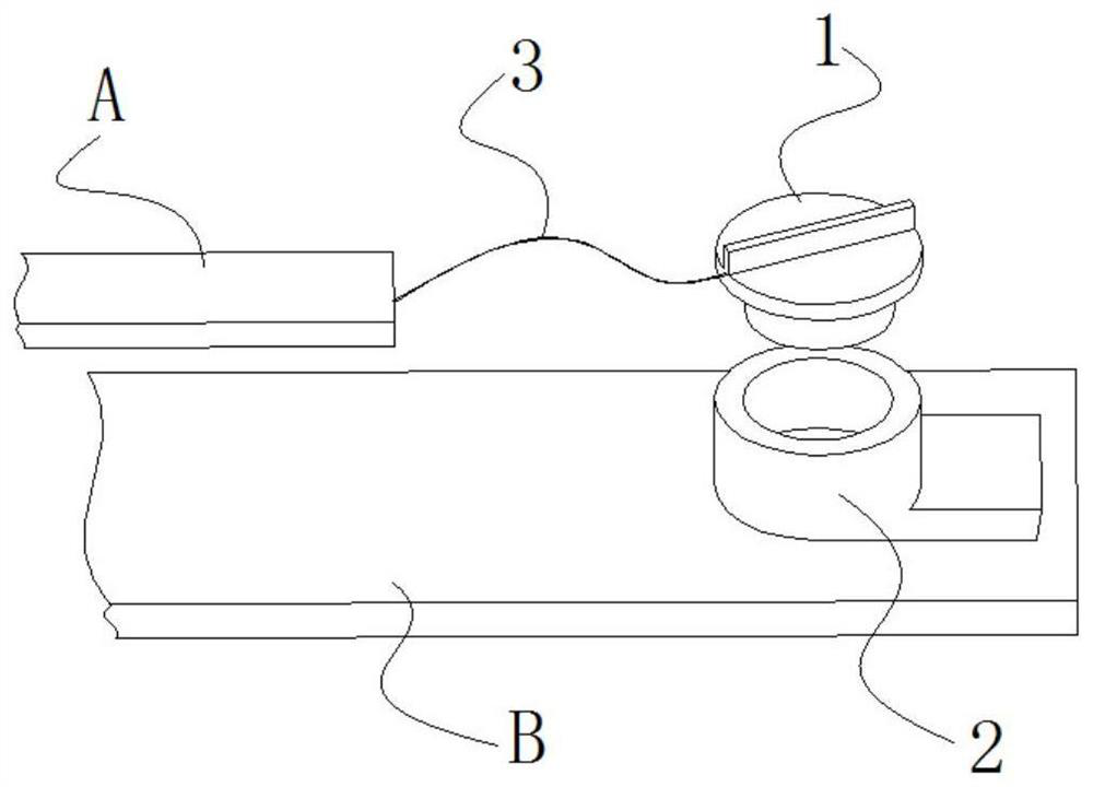
[0144] An intelligent electronic lock based on trusted identification technology, characterized in that: it includes an accessory A (1) and an accessory B (2) that can be combined with each other; the accessory A (1) and accessory B (2) are used as smart Components of electronic locks;
[0145] When the accessory A (1) is installed to the accessory B (2), the two are pressed together; the accessory A (1) has component A, and the accessory B (2) has component B; the component A ( 5) has a specific bonding surface A; the component B (4) has a specific bonding surface B;
[0146] The surface of the specific bonding surface A has several conductive contacts A; the surface of the specific bonding surface B has several conductive contacts B;
[0147] When fitting A(1) and fitting B(2) are combined, the specific bonding surface A of component A(5) is in close contact with the specific bonding surface B of component B(4); at this time, due to some or all of the conductive contacts A...
Embodiment 2
[0157] The main structure of this embodiment is the same as that of Embodiment 1. Further, the surface of the specific bonding surface A has a conductive pattern A composed of several conductive contacts A; the surface of the specific bonding surface B has a conductive pattern A composed of several conductive contacts B. Conductive pattern B;
[0158] When accessory A(1) is installed to accessory B(2), and part A(5) on accessory A(1) is combined with part B(4) on accessory B(2), the specific bonding surface A and the specific bonding surface B is in close contact; at this time, because part or all of the conductive contacts A are in contact with the conductive contacts B, in the conductive pattern A, some of the conductive contacts A are connected to each other, and the connection relationship of each conductive contact A forms information A; at the same time, because part or all of the conductive contacts B are in contact with the conductive contacts A, in the conductive patt...
Embodiment 3
[0169] The main structure of this embodiment is the same as that of Embodiment 1, and further, the surface of the specific bonding surface A has a number of conductive contacts A, when the component A (5) is not combined with the component B (4) and the component A (5) is electrified , the potential of the conductive contact A is 1; the surface of the specific bonding surface A has several grounding contacts A0; (5) When combined and component B (4) is energized, the potential of the conductive contact B is 1; the surface of the specific joint surface B has several grounding contacts B0;
[0170] When fitting A(1) is installed to fitting B(2), and part A(5) of fitting A(1) is combined with part B(4) of fitting B(2), the specific bonding surface A and the specific bonding surface B are tightly Contact; at this time, let part A (5) be energized, because part or all of the conductive contact A is in contact with the conductive contact B, which may make part or all of the conducti...
PUM
| Property | Measurement | Unit |
|---|---|---|
| Circumferential width | aaaaa | aaaaa |
Abstract
Description
Claims
Application Information