Multi-bus interconnection self-identification method and device

A self-identification, multi-bus technology, applied in the direction of circuit devices, emergency protection circuit devices, parts of emergency protection devices, etc., to achieve the effect of correct selection, high identification accuracy, and guaranteed selectivity

Pending Publication Date: 2021-03-02
BEIJING SIFANG JIBAO AUTOMATION +1
View PDF10 Cites 0 Cited by
  • Summary
  • Abstract
  • Description
  • Claims
  • Application Information

AI Technical Summary

Problems solved by technology

[0005] In order to solve the problems existing in the prior art, the purpose of the present invention is to provide a method and device for multi-bus interconnection self-identification to solve the problem of correct identification of faulty buses when interconnection occurs under complex main wiring, and is successfully applied to complex main wiring. It is also suitable for the busbar protection device of simple main wiring

Method used


Image

  • Multi-bus interconnection self-identification method and device
  • Multi-bus interconnection self-identification method and device
  • Multi-bus interconnection self-identification method and device

Examples


Embodiment 1

[0052] Figure 4 It is a schematic diagram of complex main wiring, M1~M6 are six-section busbars, L1~L3 are ordinary branch circuits, B1 is bus tie, and T1 is a span bar. L1 is connected to M1 and M2, L2 is connected to M1 and M4, L3 is connected to M5 and M6, T1 is connected to M1 and M3, the left side of B1 is connected to M3 and M4, and the right side of B1 is connected to M5. L1 to L3 correspond to 3 nodes, T1 corresponds to 1 node, the left side of B1 corresponds to 1 node, and the right side of B1 corresponds to 1 node, a total of six nodes. The present invention is applicable to the number of nodes greater than or equal to 2 with no upper limit and the number of bus sections greater than or equal to 1 with no upper limit. Figure 4 For example only.

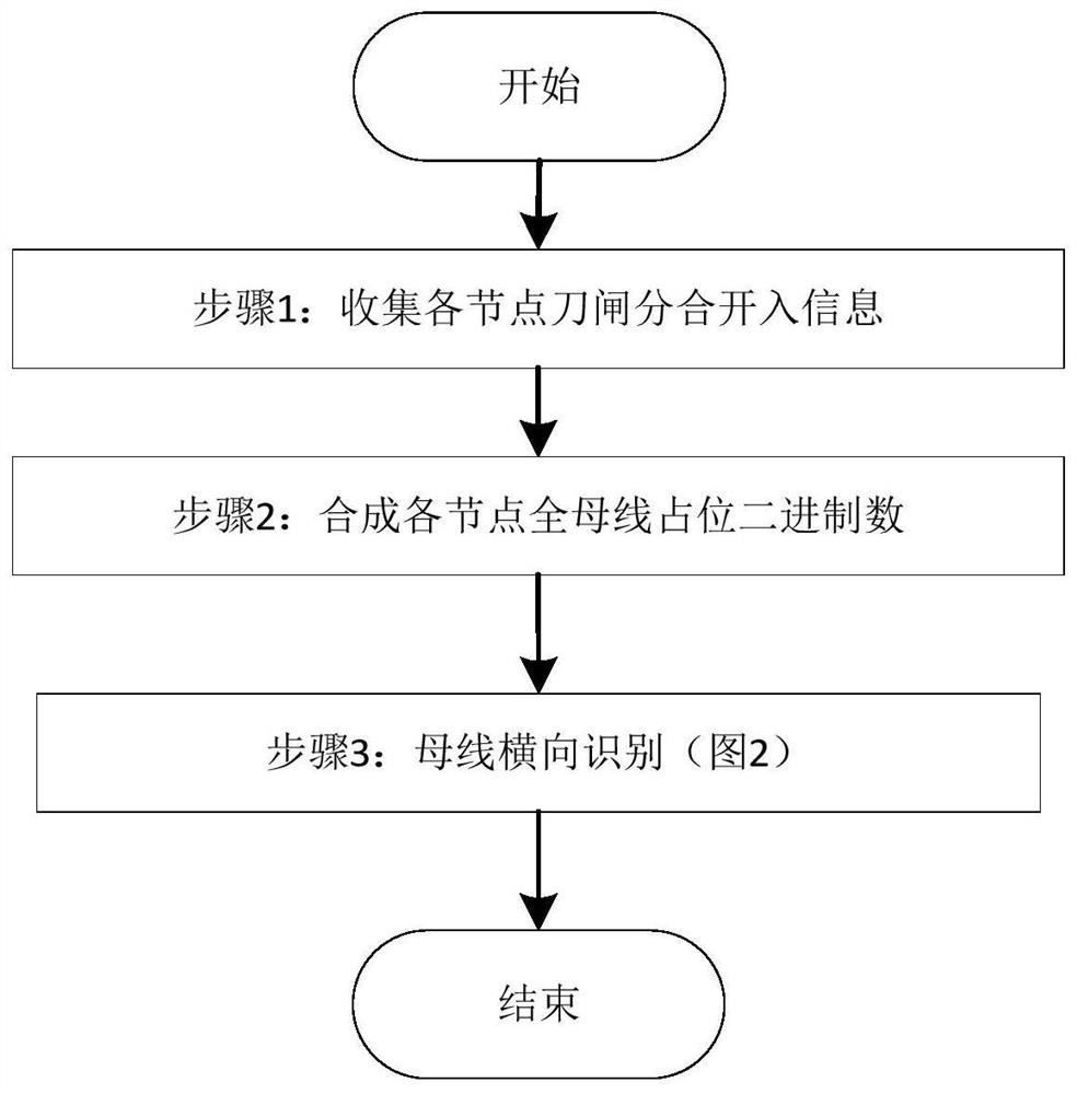
[0053] according to figure 1 The overall flow diagram of the present invention, a method for multi-bus interconnection self-identification comprises the following steps:

[0054] Step 1. According to the configuration ...

Embodiment 2

[0091] Figure 5 It is a typical double-bus wiring diagram for simple main wiring. M1 and M2 are two bus sections, L1 and L2 are ordinary branches, and B1 is a bus tie. L1 mounts M1 and M2. L1 and L2 correspond to two nodes, the left side of B1 corresponds to one node, and the right side of B1 corresponds to one node, a total of four nodes. The present invention is applicable to the number of nodes greater than or equal to 2 and no upper limit, the number of bus sections greater than or equal to 1 and no upper limit, Figure 5 For example only.

[0092] according to figure 1 The overall flow diagram of the present invention, a method for multi-bus interconnection self-identification comprises the following steps:

[0093] Step 1. According to the configuration of the four nodes, the two-section busbar switch is opened and the statistics are made on the switch opening and closing information of the four nodes on the two-section busbar in the jurisdiction area M1 and M2 of t...


PUM


Abstract

The invention discloses a multi-bus interconnection self-recognition method, and the method comprises the steps: collecting the bus knife switch opening and closing input information of each node in ajurisdiction region of a bus protection device; according to the obtained disconnecting link opening and closing information of the bus of each node, synthesizing a full-bus occupation binary numberof each node, wherein each single node is associated with one full-bus occupation binary number; in the jurisdiction area of the bus protection device, executing multiple times of bus transverse identification, wherein one time of bus transverse identification comprises multiple times of node longitudinal identification. According to the method provided by the invention, bus interconnection analysis self-adaption under different main wiring and operation modes of the bus can be realized through software, a bus fault is ensured to occur in a multi-bus wiring complex interconnection mode, a fault bus area can be correctly selected, and four requirements of relay protection are met.

Description

technical field [0001] The invention belongs to the field of relay protection of electric power systems, and relates to a self-identification method and device for multi-bus interconnection. Background technique [0002] The busbar is an important part of the power system. In order to ensure the safe and stable operation of the power system, the busbar protection is an important system equipment to ensure the safe and stable operation of the power grid, and it is of decisive significance to ensure the safety of the entire regional power grid. Therefore, it is very necessary to set up bus protection with reliable action and good performance, so that it can quickly detect the fault of the bus and remove the fault in time and selectively. [0003] Busbar protection is based on Kirchhoff's current law. When any two or more sections of busbars are interconnected, the current collected by the CT of the node where the busbar is located and entering the protection device cannot full...

Claims


Application Information

Patent Timeline
IPC IPC(8): H02H7/22H02H1/00
CPCH02H7/22H02H1/0092
Inventor 孙娴宋小舟肖远清杨卉卉
Owner BEIJING SIFANG JIBAO AUTOMATION
Why Eureka
Try Eureka