Sitting posture vision correction method and intelligent posture corrector
A technology for vision correction and posture correcting devices, which is applied in the field of posture correcting devices, can solve problems such as poor comfort, no voice prompt function of posture correcting devices, and inability to adjust angles and heights, and achieve good preventive effects
- Summary
- Abstract
- Description
- Claims
- Application Information
AI Technical Summary
Problems solved by technology
Method used
Image
Examples
Embodiment 1
[0051] A method for correcting vision in a sitting position, comprising
[0052] S1 and desktop fixed
[0053] The fixing mechanism clamps and connects the posture corrector on the desktop;
[0054] S2 Tilt Angle Adjustment
[0055] The support bar is tilted toward the side of the body, and the support bar has an angle with the horizontal line, so that the support plate on the posture correction device is against the student's chest, the student's body is a standard distance from the tabletop with a punch, and the student's eyes are one foot away from the tabletop distance;
[0056] S4 height adjustment
[0057] By moving the lifting guide rod on the support rod, adjust the posture corrector to a suitable height, and the positioning pin in the control switch is snapped into the positioning hole, and the lifting guide rod is connected with the rotating drum. Students of different heights can adjust according to the posture corrector. to the most suitable position;
[0058]...
Embodiment 2
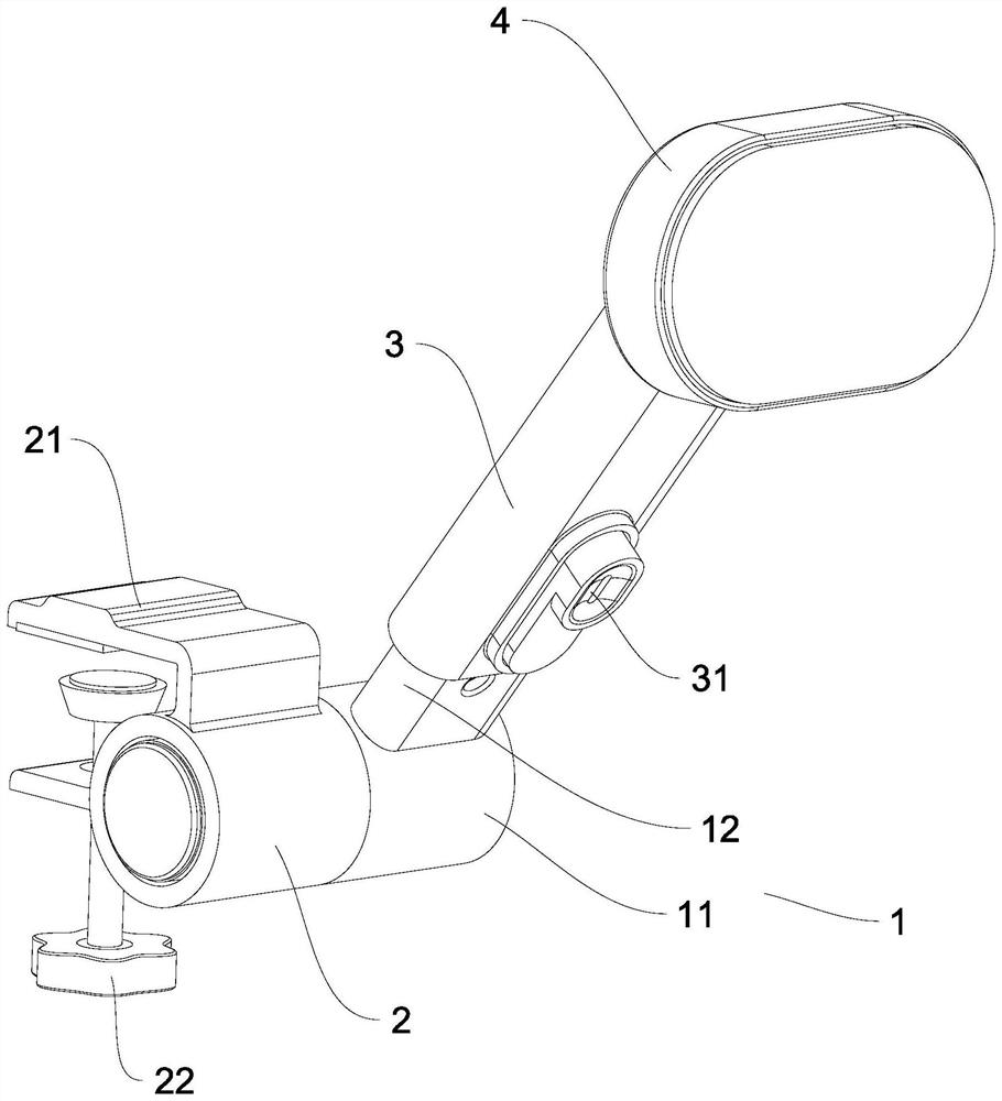
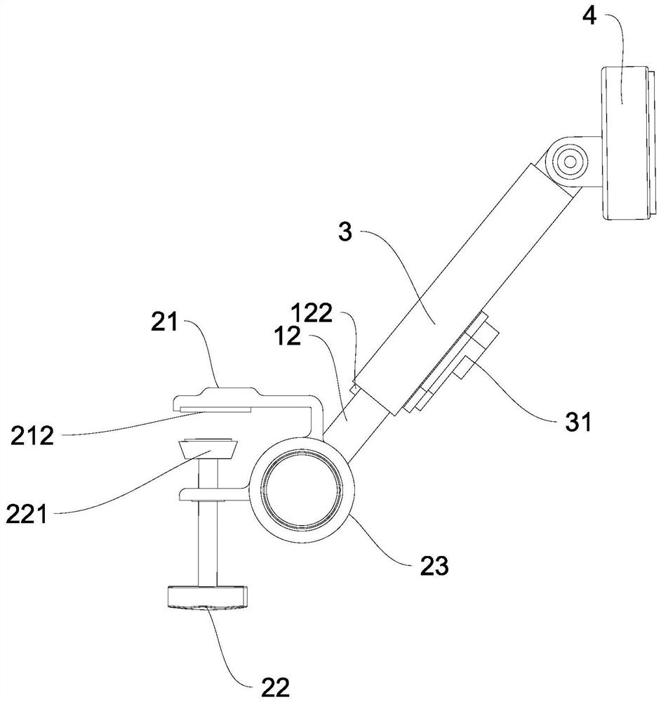
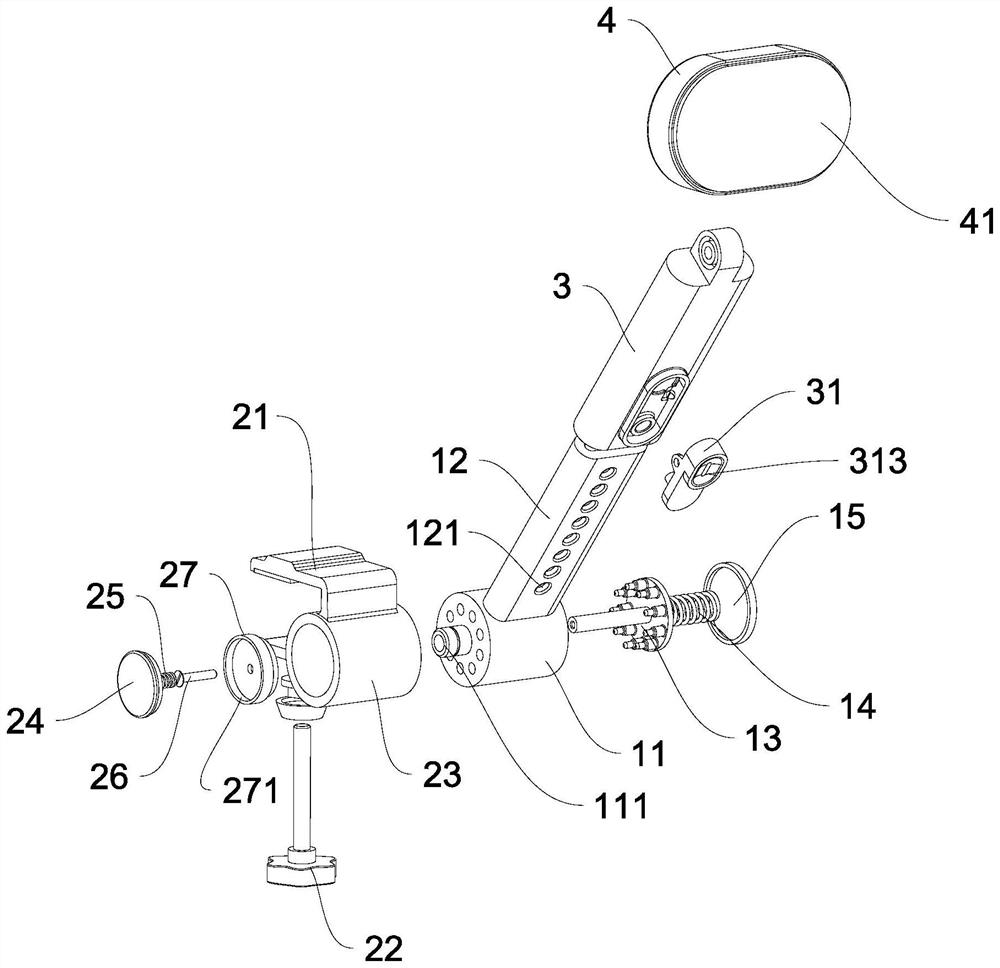
[0068] Rotating mechanism 1, said rotating mechanism 1 comprises rotating cylinder 11 and support rod 12, and supporting rod 12 is connected with rotating cylinder 11, and described supporting rod 12 forms an inclined angle with desktop, and described supporting rod 12 is provided with positioning hole 121;
[0069] A fixing mechanism 2, which is rotatably connected to the drum 11, and the fixing mechanism 2 is used to fix the posture corrector on the desktop;
[0070] Lifting guide rod 3, the lifting guide rod 3 is slidingly sleeved on the outside of the support rod 12, the lifting guide rod 3 is provided with a control switch 31, the control switch 31 is provided with a positioning pin 33, and the positioning pin 33 Insert into the positioning hole 121;
[0071] Supporting plate 4, described supporting plate 4 is rotationally connected with the upper end of lifting guide rod 3;
[0072] An intelligent module, the intelligent module includes a power processing module, a con...
Embodiment 3
[0078] Such as figure 1 , figure 2 , image 3 , Figure 5 , Figure 6 and Figure 7 As shown, the drum 11 is provided with a rotating clip 13, a spring 14 and a right end cover 15, the center of the left end face of the drum 11 is provided with a hollow positioning column 111, and the ring on the left end face of the drum 11 is provided with Round hole one 112, a connecting post 131 is provided on the center of the rotary clip 13, a clip post 132 is provided on the upper ring of the rotary clip 13, the spring one 14 is located on the right side of the rotary clip 13, and the right end The cover 15 is clamped to the inner groove 113 of the drum 11;
[0079] Described fixing mechanism 2 comprises U-shaped splint 21 and fastening bolt 22, sleeve 23, left end cap 24, spring two 25, bolt 26 and guide block 27, and described fastening bolt 22 is located in U-shaped splint 21 threaded holes , the sleeve 23 is integrally formed and connected with the U-shaped splint 21, the cen...
PUM
 Abstract
Description
Claims
Application Information
 - R&D
- Intellectual Property
- Life Sciences
- Materials
- Tech Scout
- Unparalleled Data Quality
- Higher Quality Content
- 60% Fewer Hallucinations
Browse by: Latest US Patents, China's latest patents, Technical Efficacy Thesaurus, Application Domain, Technology Topic, Popular Technical Reports.
© 2025 PatSnap. All rights reserved.Legal|Privacy policy|Modern Slavery Act Transparency Statement|Sitemap|About US| Contact US: help@patsnap.com


