a cooking utensil

A technology of cooking utensils and couplings, applied in the field of cooking utensils, can solve the problems of inconvenient storage and transportation, inconvenient cleaning and taking, and affecting user experience, etc., to achieve convenient picking and assembly operations, stable and reliable connection and rotation , Improve the effect of user experience

Active Publication Date: 2022-03-18
JOYOUNG CO LTD
View PDF0 Cites 0 Cited by
  • Summary
  • Abstract
  • Description
  • Claims
  • Application Information

AI Technical Summary

Problems solved by technology

However, most of the stirrers of cooking machines sold in the existing market protrude from the pot cover, which leads to a large space occupation. The stirrer has no locking structure. It is inconvenient to transport, clean, and place; and when there are ingredients in the pot, the stirring device interferes with the ingredients, which may cause splashing of ingredients and problems with the lid of the pot, affecting user experience

Method used


Image

  • a cooking utensil
  • a cooking utensil
  • a cooking utensil

Examples


Embodiment 1

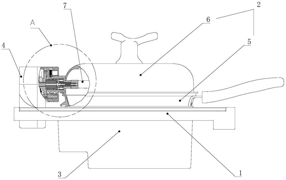
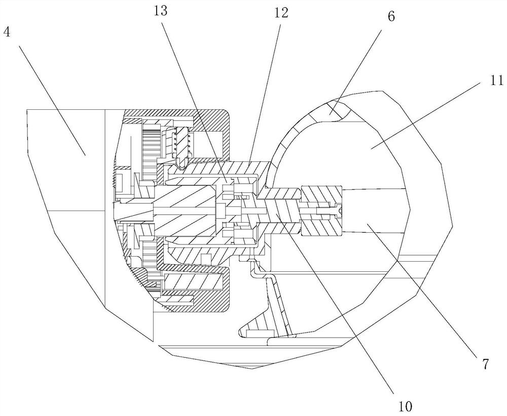
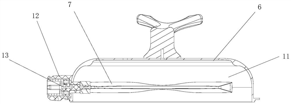
[0044] Such as Figure 1-2 As shown, the embodiment proposes a cooking utensil, which includes a machine base 1, a pot body assembly 2, a heating assembly 3, and a power mechanism 4. The pot body assembly 2 includes a pot body 5 and a pot cover 6 that is closed on the pot body . Wherein, the pot body assembly 2 is provided with a stirring member 7 rotating around the rotating shaft 10, the pot body assembly 2 is supported on the machine base 1, the pot cover 6 is closed on the pot body assembly 2, and the stirring member 7 extends into the pot body assembly 2 Inside, the power mechanism 4 is arranged on the machine base 1, the heating assembly 3 is located under the pot body assembly 2, and the pot body assembly 2 is provided with a locking part 8 and a limit part 9; the stirring member 7 is detachably connected with the power mechanism 4, and the power The output shaft of the mechanism 4 drives the stirring member 7 to swing in the pot body assembly 2, and stirs the ingredie...

Embodiment 2

[0061] The difference between this embodiment and the first embodiment lies in that the structures of the locking part 8 and the limiting part 9 are different.

[0062] Such as Figure 9 with Figure 10 As shown, the locking part 8 is a positioning bead slidably arranged in the first mounting hole 15, and the coupling 13 is also provided with a second reset part 23 between the bottom of the first mounting hole 15 and the positioning bead, and the second reset part 23 faces The positioning bead generates a force protruding from the first end face 14 . The limiting part 9 is a positioning hole provided on the mating surface corresponding to the mounting hole, and the positioning hole is a positioning groove arranged along the axial direction of the rotating shaft 10 , and a guiding slope 24 is provided on the outside of the positioning groove along the rotation direction of the coupling 13 .

[0063] Specifically, when the coupling 13 is separated from the power mechanism 4, t...

Embodiment 3

[0066] The difference between this embodiment and the first embodiment is that the locking component 8 and the limiting portion 9 are arranged radially along the rotating shaft 10 .

[0067] Such as Figure 11-13 As shown, the locking structure includes a locking component 8 and a limiting portion 9 arranged in sequence along the radial direction of the rotating shaft 10, and the locking component 8 can move relative to the limiting portion 9 along the radial direction of the rotating shaft 10, and is connected with the limiting portion 9 Or separate to lock the stirring member 7 at the set position or unlock the stirring member 7. The locking part 8 and the limiting part 9 are sequentially arranged along the radial direction of the rotating shaft 10, which is beneficial to shortening the length of the rotating shaft 10, making the structure more compact and reducing space occupation. The rotating shaft 10 has higher strength, more stable and reliable rotation, and better user...


PUM


Abstract

The invention provides a cooking utensil, comprising a machine base and a pot body assembly supported on the machine base, the pot body assembly is provided with a stirring member rotating around a rotating shaft, and the machine base is provided with a power mechanism, so The agitator is detachably connected to the power mechanism, and the pot body assembly is provided with a locking part and a limiting part. When the stirring part is disengaged from the power mechanism, the locking part and the limiting part Cooperate and lock to lock the stirrer at the set position; the stirrer is cooperatively connected with the power mechanism, the locking part is unlocked from the limiting part, and the stirrer is in the position of the power mechanism Driven to rotate and stir. The cooking utensil of the present invention has a simple structure, is convenient to clean, and effectively improves user experience.

Description

technical field [0001] The invention relates to the field of kitchen appliances, in particular to a cooking utensil. Background technique [0002] The existing cooking machine is equipped with a stirring device to continuously stir the ingredients in the pot to realize the stir-frying of the ingredients, so that the ingredients are cooked, which can replace part of the manual operation, automatically complete the cooking function, and free the user's hands. However, most of the stirrers of cooking machines sold in the existing market protrude from the pot cover, which leads to a large space occupation. The stirrer has no locking structure. It is inconvenient to transport, clean, and place; and when there are ingredients in the pot, the stirring device interferes with the ingredients, which may cause splashing of ingredients and problems with the lid of the pot, affecting user experience. Contents of the invention [0003] The purpose of the present invention is to provide...

Claims


Application Information

Patent Timeline
Patent Type & Authority Patents(China)
IPC IPC(8): A47J27/00A47J36/06A47J36/16
CPCA47J27/00A47J36/165A47J36/06
Inventor 王旭宁刘孝碧
Owner JOYOUNG CO LTD
Why Eureka
Try Eureka