Three-piece type pop-top can top cover mounting equipment

A technology for installing equipment and cans, which is applied in the field of three-piece can top installation equipment, can solve the problems of manual operation, cumbersome operation, and low installation efficiency, and achieve the effects of reducing labor, simple operation, and improving installation efficiency

Inactive Publication Date: 2021-03-05
王燕华
View PDF6 Cites 2 Cited by
  • Summary
  • Abstract
  • Description
  • Claims
  • Application Information

AI Technical Summary

Problems solved by technology

[0005] In order to overcome the disadvantages that the current installation of the top cover of the three-piece pop can needs to be done manually, the operation is cumbersome and the installation efficiency is low, the technical problem to be solved by the invention is to provide an , Three-piece can top cover installation equipment that can improve installation efficiency

Method used


Image

  • Three-piece type pop-top can top cover mounting equipment
  • Three-piece type pop-top can top cover mounting equipment
  • Three-piece type pop-top can top cover mounting equipment

Examples


Embodiment 1

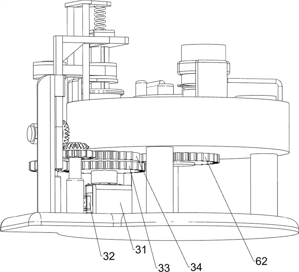
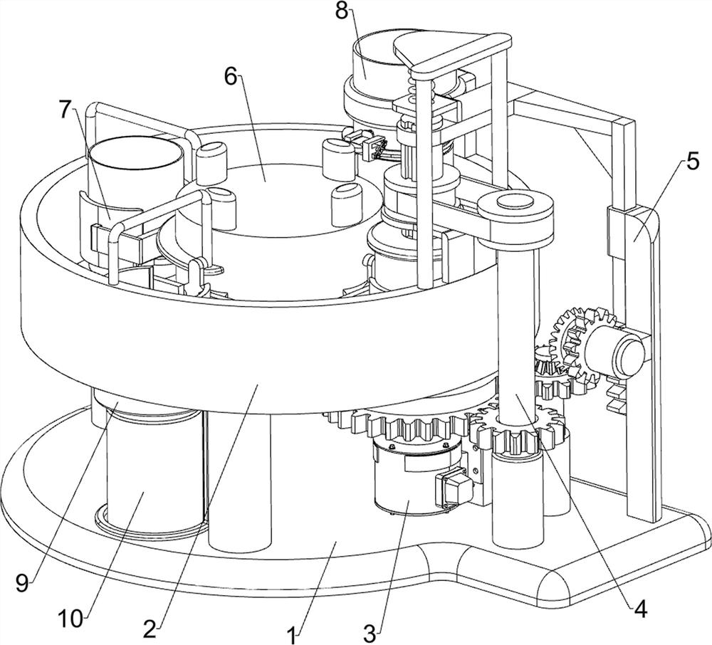
[0029] A three-piece can top installation device, such as Figure 1-4 As shown, it includes a bottom plate 1, a placement table 2, a driving mechanism 3, a rotating mechanism 4 and a capping mechanism 5. The top left side of the bottom plate 1 is connected with a placement table 2, and the top of the bottom plate 1 is equipped with a driving mechanism 3. The bottom plate 1 and the placement table A capping mechanism 5 is installed between the two, and the capping mechanism 5 is connected to the drive mechanism 3 in transmission.

[0030] The driving mechanism 3 includes a fixed plate 31, a servo motor 32, a first gear 33 and a sector gear 34. The bottom right side of the top of the bottom plate 1 is connected with a fixed plate 31, and the fixed plate 31 is equipped with a servo motor 32. The output shaft of the servo motor 32 The first gear 33 and the sector gear 34 are respectively connected through a coupling, and the sector gear 34 is located on the upper side of the first...

Embodiment 2

[0035] On the basis of Example 1, such as Figure 2-5 As shown, a moving mechanism 6 is also included. The moving mechanism 6 includes a rotating column 61 and a fifth gear 62. The middle of the bottom of the placement platform 2 is connected to the rotating column 61 in a rotational manner, and the bottom end of the rotating column 61 is connected to the fifth gear 62. The fifth gear 62 meshes with the sector gear 34 .

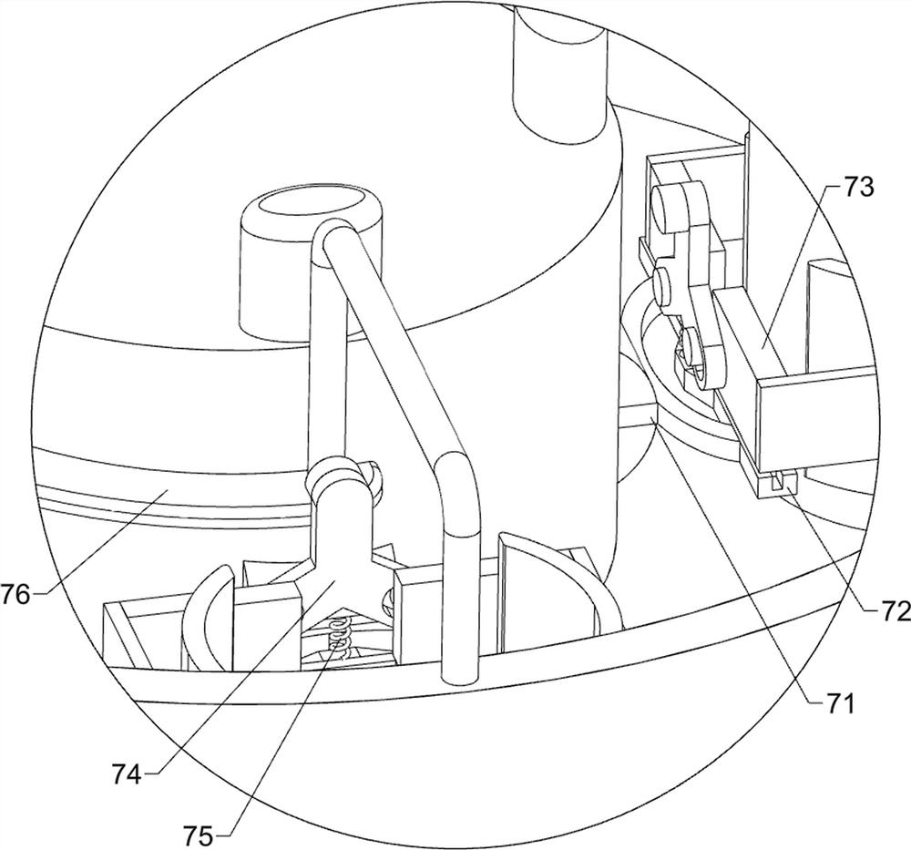
[0036] Also includes a clamping mechanism 7, the clamping mechanism 7 includes a mounting frame 71, a guide rail frame 72, a sliding splint 73, a three-head push block 74, a second return spring 75 and a fixed top plate 76, and the middle part of the outer wall of the rotating column 61 is along the circumferential direction. There are four mounting brackets 71 evenly spaced connected, the mounting bracket 71 is connected with a guide rail frame 72, two sliding splints 73 are slidably connected in the guide rail frame 72, and three push blocks 74 are slidingl...

Embodiment 3

[0039] On the basis of Example 2, such as image 3 and Figure 6 As shown, a top cover placement mechanism 8 is also included, and the top cover placement mechanism 8 includes a fixed collar frame 81, a storage barrel 82, a guide frame 83, a first baffle plate 84, a second baffle plate 85, a central axis 86, Slotted connecting rod 87, push plate 88, the third back-moving spring 89 and top block 810, the rear side of placing platform 2 top is connected with fixed collar frame 81, is connected with storage barrel 82 in the fixed collar frame 81, and storage barrel The lower part of the front side of 82 is connected with guide frame 83, and the lower side sliding type in the guide frame 83 is connected with the first baffle plate 84, and the first baffle plate 84 contacts and cooperates with the bottom of material storage barrel 82, and the upper side sliding type in the guide frame 83 A second baffle plate 85 is connected, and the second baffle plate 85 is slidably connected wi...


PUM


Abstract

The invention relates to top cover mounting equipment, in particular to three-piece type pop-top can top cover mounting equipment. The three-piece type zip-top can top cover mounting equipment is easyto operate, capable of automatically feeding and discharging and capable of improving the mounting efficiency. The three-piece type pop-top can top cover mounting equipment comprises a bottom plate,a driving mechanism, a cover pressing mechanism and a rotating mechanism, wherein a placing table is connected to one side of the bottom plate; the driving mechanism is mounted on the bottom plate; acover pressing mechanism is mounted between the bottom plate and the placing table, and the cover pressing mechanism is in transmission connection with the driving mechanism; and the rotating mechanism is mounted between the bottom plate and the cover pressing mechanism, and the rotating mechanism is in transmission connection with the driving mechanism. All the mechanisms can be driven to operatethrough the driving mechanism, and a top cover can be fixedly mounted on a tank body through cooperation of the rotating mechanism and the cover pressing mechanism.

Description

technical field [0001] The invention relates to a top cover installation device, in particular to a three-piece pop can top cover installation device. Background technique [0002] Pop-top cans are composed of three aluminum alloys with different compositions, and consist of a can body, a can lid and a pull ring. The three-piece can is divided into three parts: the top cover, the can body, and the bottom cover. The three-piece can needs to be installed on the top cover before the food can be filled in the three-piece can; currently, the top of the three-piece can is The cap installation is generally carried out with manual assistance. First, the top cap is manually placed on the can body, and then the can body is put into the top cap installation equipment. After the installation is completed, the can body is manually taken out from the top cap installation equipment. The operation is cumbersome, the labor load of the workers is large, the labor intensity is high, and the w...

Claims


Application Information

Patent Timeline
Patent Type & Authority Applications(China)
IPC IPC(8): B67B3/20B65G47/82B65G29/00
CPCB67B3/20B67B3/206B65G47/82B65G29/00
Inventor 王燕华
Owner 王燕华
Why Eureka
Try Eureka