Adjustable veneer mounting structure
A technology for installing structures and decorative panels, applied in building construction, covering/lining, construction, etc., can solve the problems of inability to adjust and expand, small scope of application, single structure, etc., to reduce installation costs, labor costs, and flexible adjustment. Effect
- Summary
- Abstract
- Description
- Claims
- Application Information
AI Technical Summary
Problems solved by technology
Method used
Image
Examples
Embodiment 1
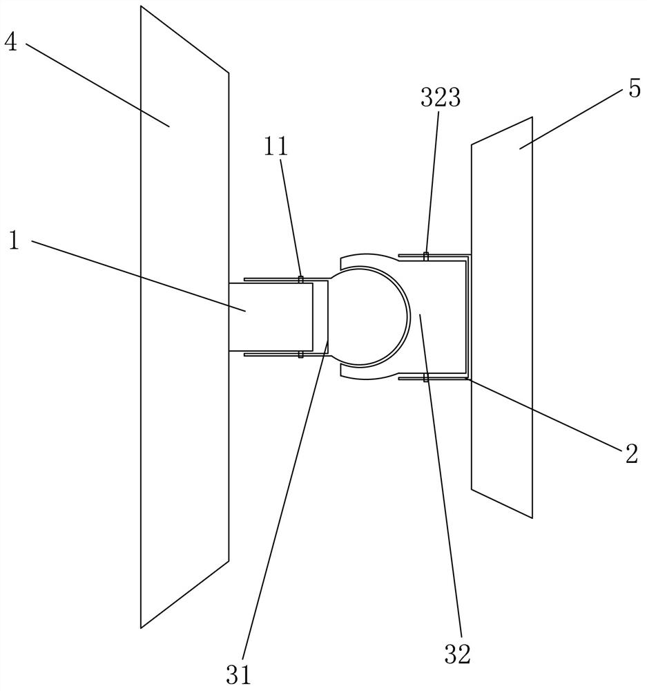
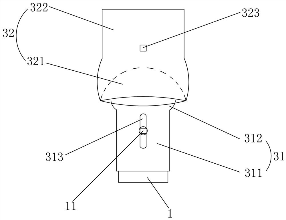
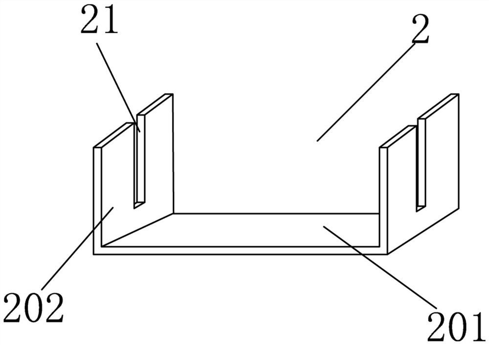
[0030] Embodiment one: if Figures 1 to 3 As shown, it is only one embodiment of the present invention, an adjustable decorative panel installation structure, including a bottom piece 1 connected with a base 4, a clip 2 connected with a decorative panel 5, and a bottom piece for connecting the bottom piece. 1 and the functional part 3 of the clip 2, the functional part 3 includes a first part 31 connected with the bottom part 1 and a second part 32 connected with the clip 2, the first part 31 is close to One end of the bottom part 1 is provided with a sleeve 311, at least a part of the bottom part 1 is located in the sleeve 311, and one end of the first part 31 close to the second part 32 is provided with a spherical protrusion 312 , the second part 32 is provided with a concave spherical groove 321 near the end of the first part 31, and the end of the second part 32 near the clip 2 is provided with a plane post 322, and the spherical protrusion 312 has at least Half of it is...
Embodiment 2
[0047] Embodiment two, still as Figures 1 to 3 As shown, it is only one of the embodiments of the present invention. On the basis of the first embodiment, in the installation structure of the adjustable decorative panel of the present invention, the first part 31 and the second part 32 are integrally formed. pieces. In this way, the structural stability of the rotation between the first part 31 and the second part 32 is strong, and the carrying capacity of the decorative panel 5 is strong.
[0048] It should also be noted that the cold shrinkage coefficient of the first piece 31 is greater than the cold shrinkage coefficient of the second piece 32 . In fact, the cold shrinkage coefficient of the spherical protrusion 312 is greater than that of the concave spherical groove 321, and the spherical protrusion 312 shrinks when it is cooled, so that its diameter is smaller than the opening of the concave spherical groove 321, and the spherical convex 312 is inserted into the conc...
PUM
 Abstract
Description
Claims
Application Information
 - R&D
- Intellectual Property
- Life Sciences
- Materials
- Tech Scout
- Unparalleled Data Quality
- Higher Quality Content
- 60% Fewer Hallucinations
Browse by: Latest US Patents, China's latest patents, Technical Efficacy Thesaurus, Application Domain, Technology Topic, Popular Technical Reports.
© 2025 PatSnap. All rights reserved.Legal|Privacy policy|Modern Slavery Act Transparency Statement|Sitemap|About US| Contact US: help@patsnap.com


