
Humidifier and control method thereof

A control method and humidifier technology, applied in the direction of chemical instruments and methods, heating methods, air humidification systems, etc., can solve the problems of hidden dangers harmful to the human body, non-killing, material aging, etc., and achieve the goal of improving user experience and water quality Effect

Inactive Publication Date: 2021-03-05
GREE ELECTRIC APPLIANCES INC
View PDF10 Cites 2 Cited by
  • Summary
  • Abstract
  • Description
  • Claims
  • Application Information

AI Technical Summary

Problems solved by technology

The water in the humidifier is generally not used up all at once, so if the water in the humidifier is left for a long time, bacteria will easily breed, pollute the air after atomization, and endanger human health
At present, humidifier sterilization technology is also used in some humidifiers, but most of them use antibacterial agents to sterilize. This kind of bactericide has poor sterilization effect and needs to be replaced regularly, which may be harmful to the human body.
In addition, some also use ultraviolet lamp technology. This technology is mainly used to kill the bacteria that grow in the water tank, but it has no effect on the bacteria that grow in the tank. In addition, ultraviolet light has aging problems on the material, which will affect the use of the humidifier. life
[0003] Humidifiers generally use tap water, which often contains residual chlorine and disinfection by-products. These organic substances generally have a low boiling point. After atomization, they are easy to disperse in the air with water droplets, thus polluting the air quality.
In addition, the hardness of tap water is generally high, and a humidifier that uses tap water for a long time is likely to form a layer of white powdery scale on the surface, which affects the performance of the humidifier.

Method used


Image

  • Humidifier and control method thereof
  • Humidifier and control method thereof

Examples


Embodiment Construction

[0022] In order to better understand the purpose, structure and function of the present invention, a humidifier and its control method of the present invention will be further described in detail below in conjunction with the accompanying drawings.

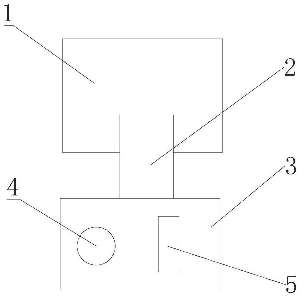
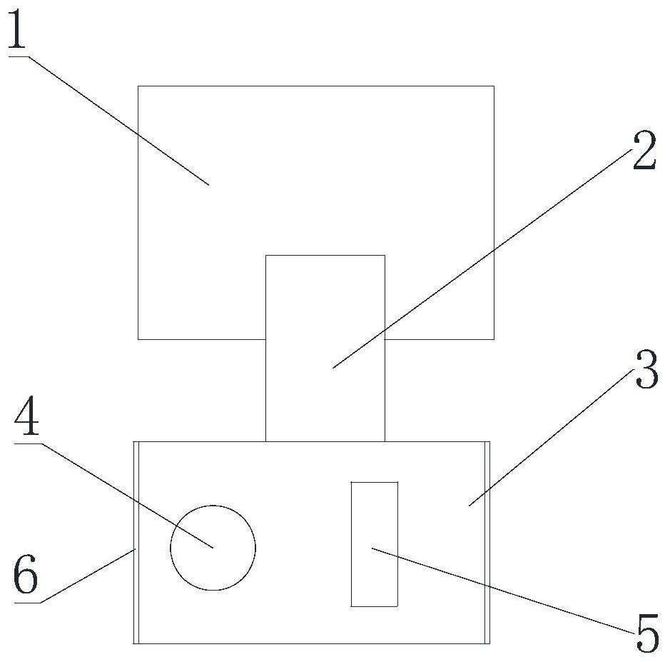
[0023] Such as figure 1 As shown, the humidifier of the present invention includes a water tank 1, a water tank 3 and an atomizing device 4 for atomizing the water in the water tank 3. A water supply flow path is provided between the water tank 1 and the water tank 3, and the water tank 1 can pass through The water supply flow path replenishes water to the water tank 3, and the humidifier also includes a sterilizing device for sterilizing the water in the water tank 3, so as to effectively ensure the sterilizing effect of the water in the humidifier.

[0024] Preferably, the sterilizing device includes ozone sterilizing device, heat sterilizing device, ultraviolet lamp 5 and / or water catalyst device and other sterilizing devices, ...


PUM


Abstract

The invention discloses a humidifier. The humidifier comprises a water tank, a water channel and an atomization device used for atomizing water in the water channel; a water supply flow path is arranged between the water tank and the water channel; the water tank supplements water to the water channel through the water supply flow path; a composite filter element is arranged on the water supply flow path; and the humidifier further comprises a sterilization device used for sterilizing the water in the water channel. The invention further discloses a control method of the humidifier. Accordingto the humidifier, the composite filter element is arranged on the water path between the water tank and the water channel, the sterilization device is arranged in the water channel, the water qualityin the water channel is purified, water tank bacteria are intercepted, water channel bacteria breeding is inhibited, the bacteria problem of the water tank and the water channel is solved, the waterquality is improved, pure physical purification and sterilization are safe and reliable, water sterility is guaranteed, the air cannot be polluted, and the user experience is greatly improved.

Description

technical field [0001] The invention relates to a humidifier, in particular to a humidifier and a control method thereof. Background technique [0002] With the improvement of people's living conditions, humidifiers have become an essential small appliance for most families, especially those in the northern region. The water in the humidifier is generally not used up all at once, so if the water in the humidifier is left for a long time, bacteria will easily breed, pollute the air after atomization, and endanger human health. At present, humidifier sterilization technology is also used in some humidifiers, but most of them use antibacterial agents, which have poor sterilization effects and need to be replaced regularly, which may be harmful to the human body. In addition, some also use ultraviolet lamp technology. This technology is mainly used to kill the bacteria that grow in the water tank, but it has no effect on the bacteria that grow in the tank. In addition, ultravio...

Claims


Application Information

Patent Timeline
Patent Type & Authority Applications(China)
IPC IPC(8): F24F6/12F24F13/00C02F1/32C02F1/50
CPCC02F1/32C02F1/50C02F2303/04F24F6/12F24F13/00
Inventor 周平发王涛詹婷李海妃
Owner GREE ELECTRIC APPLIANCES INC
Learn More