Foldable flower stand for interior design
An interior design and flower stand technology, which is applied in the field of flower stands, can solve the problems of no flower stand and cannot grow upright, etc., and achieves the effect of being beneficial to growth and easy to assemble and fix.
- Summary
- Abstract
- Description
- Claims
- Application Information
AI Technical Summary
Problems solved by technology
Method used
Image
Examples
Embodiment 1
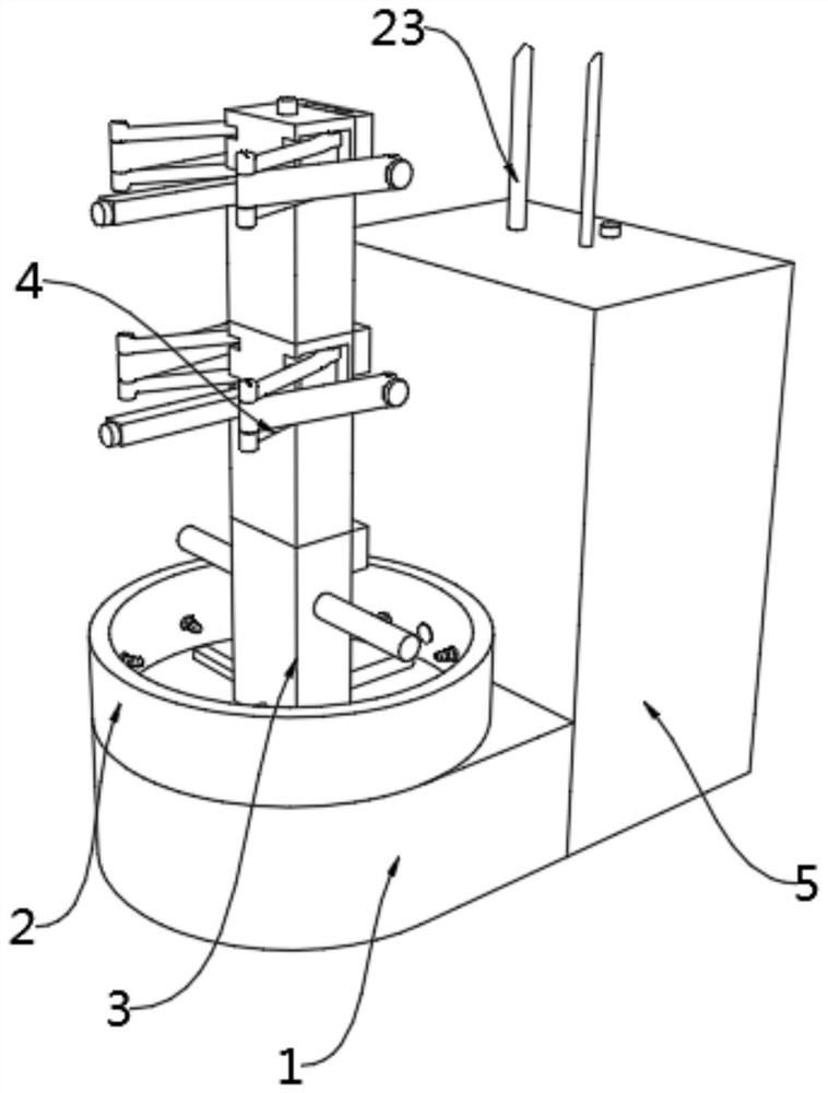
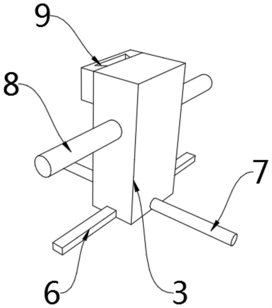
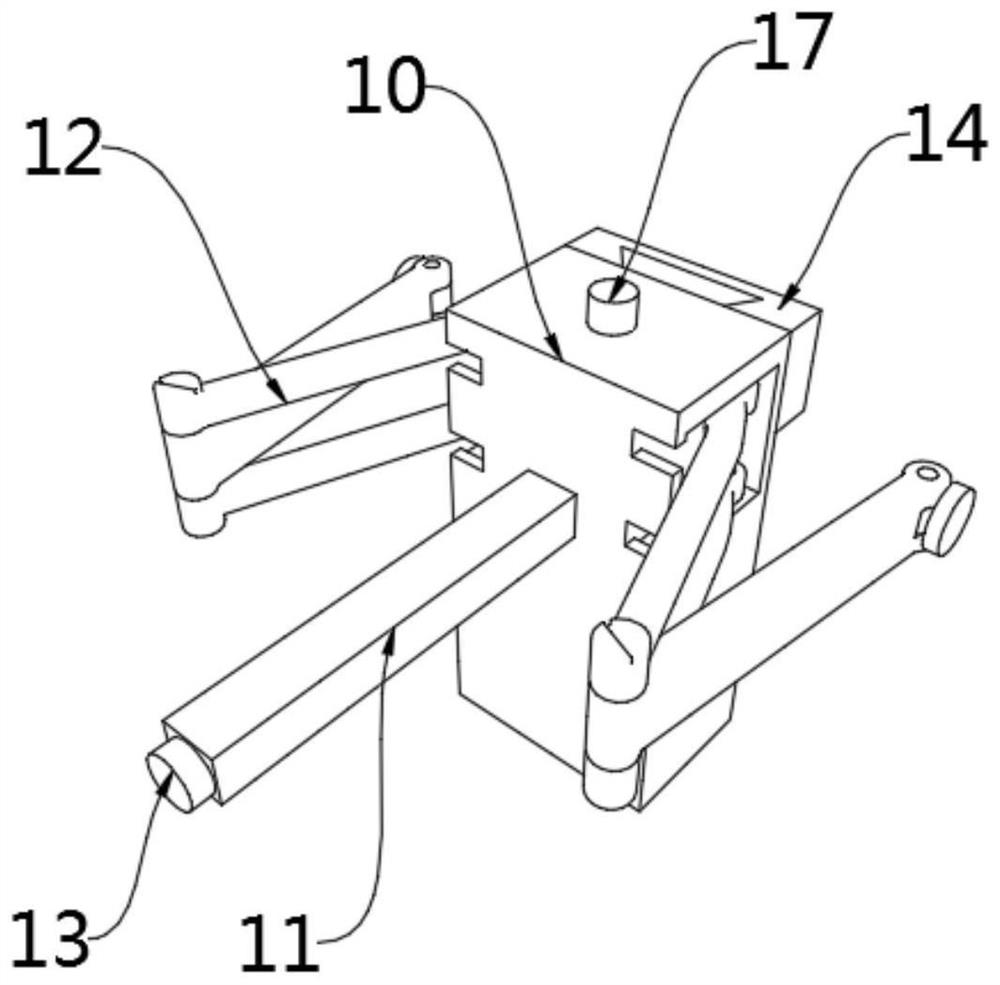
[0037] see Figure 1-11 , a foldable flower stand for indoor design according to an embodiment of the present invention, comprising a base 1, a fixed ring 2 and a fixed column 3 are fixed to the top of the base 1 in turn, and a fixed box 5 is fixed to one end of the base 1, so The top of the fixed column 3 is fixed with a support mechanism 4, and one end of the fixed column 3 is fixed with a first limiter 9, and the central axis of the fixed column 3 is fixed with a pillar 8, and the first limiter The block 9 is located at the top of the fixed column 3, and the support mechanism 4 includes a fixed block 10, a long column 11, a folding arm 12, a switch 13, a second limiting block 14, a limiting piece 15, a first motor 16, a rotating rod 17. Limit ring 18, limit rod 19, limit groove 20, fixed plate 21 and limit bar 22, folding arms 12 are connected to both sides of the fixed block 10 in rotation, and one end of the fixed block 10 is fixed with A long column 11, the end of the l...
Embodiment 2
[0040] see Figure 1-11 One end of the base 1 is fixed with a fixed box 5, and the inside of the fixed box 5 is fixed with an adjustment mechanism 23, and the adjustment mechanism 23 includes a first soil acid-base detection sensor 6, a second soil acid-base detection sensor 7, Cylindrical box 24, feed pipe 25, liquid inlet pipe 26, controller 27, first liquid outlet pipe 28, electromagnetic valve 29, water pump 30, second liquid outlet pipe 31, transport pipe 32, fixed pipe 33 and nozzle 34, The top inside the fixed box 5 is fixed with a controller 27, one side of the top of the cylindrical box 24 is fixed with a feed pipe 25, and the side of the top of the cylindrical box 24 away from the feed pipe 25 is fixed with a liquid inlet pipe 26, the bottom end of the cylindrical box 24 is fixed with a first liquid outlet pipe 28, and the peripheral side of the first liquid outlet pipe 28 is fixed with an electromagnetic valve 29, and the first liquid outlet pipe 28 is far away from...
Embodiment 3
[0043] see Figure 1-11 , the top of the fixed box 5 is fixed with a second switch, and the position of the central axis of the top of the cylindrical box 24 is fixed with a mixing mechanism 35, and the mixing mechanism 35 includes a second motor 36, a first rotating shaft 37, a first cone Gear 38, second bevel gear 39, second rotating shaft 40, third bevel gear 41, mixing blade 42, protection box 43 and reinforcing rod 44, the output end of the second motor 36 is fixed with the first rotating shaft 37, The side surface of the first rotating shaft 37 away from the end of the second motor 36 is rotatably connected with a protective box 43 through a bearing, and the end of the first rotating shaft 37 close to the protective box 43 is fixed with a first bevel gear 38, One side of the inside of the protection box 43 is rotatably connected with a second bevel gear 39, and one end of the protection box 43 away from the first bevel gear 38 is rotatably connected with a second rotatin...
PUM
 Abstract
Description
Claims
Application Information
 - R&D
- Intellectual Property
- Life Sciences
- Materials
- Tech Scout
- Unparalleled Data Quality
- Higher Quality Content
- 60% Fewer Hallucinations
Browse by: Latest US Patents, China's latest patents, Technical Efficacy Thesaurus, Application Domain, Technology Topic, Popular Technical Reports.
© 2025 PatSnap. All rights reserved.Legal|Privacy policy|Modern Slavery Act Transparency Statement|Sitemap|About US| Contact US: help@patsnap.com


