Workpiece clamping device for cooling of small workpieces

A technology for small workpieces and workpiece clamps, applied in auxiliary devices, grinding/polishing safety devices, manufacturing tools, etc., can solve the problems of increased labor intensity, lack of practicability, increased production and processing time, etc. Convenience, increased functionality, increased friction effect

Inactive Publication Date: 2021-03-09
张中秋
View PDF0 Cites 1 Cited by
  • Summary
  • Abstract
  • Description
  • Claims
  • Application Information

AI Technical Summary

Problems solved by technology

[0002] With the development of science and technology, the processing of small workpieces is becoming more and more perfect. Some small workpieces need to be polished and welded during the processing process, which makes the surface temperature of the workpiece high and it is inconvenient to remove the workpiece. Therefore, it is necessary to use a clamping device to hold the small workpiece Clamping, but the current clamping device does not have a cooling function. After clamping the workpiece, it needs to be left to cool before picking up the workpiece, which increases the length of production and processing, reduces production efficiency, and the surface of the workpiece is polished and welded. A large amount of dust is easy to adhere to, and manual cleaning is required to accurately observe the processing of the workpiece, which increases labor intensity and lacks practicability. In view of this, we propose a workpiece clamping device for cooling small workpieces

Method used


Image

  • Workpiece clamping device for cooling of small workpieces
  • Workpiece clamping device for cooling of small workpieces
  • Workpiece clamping device for cooling of small workpieces

Examples


Embodiment 1

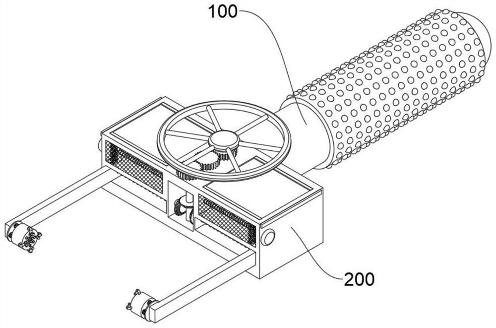
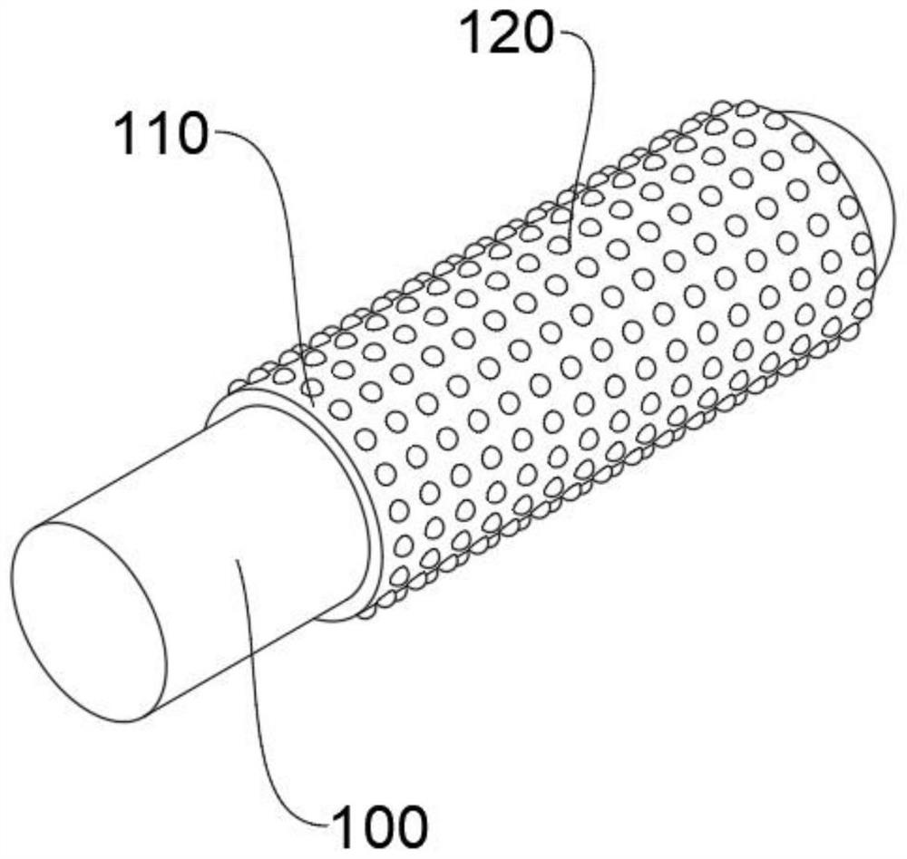
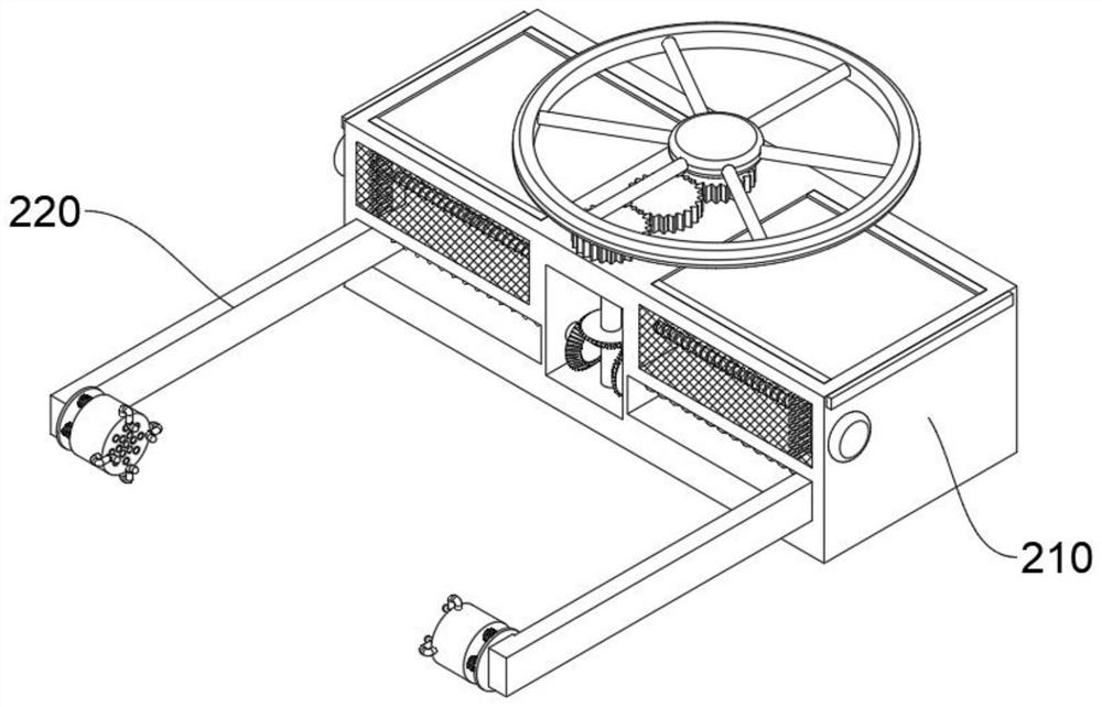
[0050] see Figure 1-Figure 16 As shown, this embodiment provides a workpiece clamping device for cooling small workpieces, including a handle 100 and a cooling clamping mechanism 200 provided at the end of the handle 100. The cooling clamping mechanism 200 includes at least:

[0051] The fixed frame 210, the front surface of the fixed frame 210 is provided with two symmetrical moving grooves 211 near the bottom, the moving screw rod 212 is arranged to rotate inside the moving groove 211, and a power groove 213 is arranged between the two moving grooves 211, and the two moving grooves 211 The ends of the screw mandrel 212 are all rotated and stretched into the power groove 213 to be connected with a first bevel gear 2120. The power groove 213 is internally rotated to be provided with a rotating rod 2131, and the outer wall of the rotating rod 2131 is fixedly provided with a second bevel gear 2132. The outer wall of the bevel gear 2132 is meshed with the outer walls of the two ...


PUM


Abstract

The invention relates to the technical field of clamping devices, in particular to a workpiece clamping device for cooling of small workpieces. The workpiece clamping device comprises a holding rod and a cooling clamping mechanism arranged at the end of the holding rod, the cooling clamping mechanism at least comprises a fixing frame, two symmetrical moving grooves are formed in the positions, close to the bottom, of the front surface of the fixing frame, moving lead screws and clamping devices are rotationally arranged in the moving grooves, each clamping device comprises a moving plate, anda moving lead screw hole is formed in the surface, close to the end, of each moving plate; each movable screw hole is in threaded fit connection with the outer wall of the corresponding movable screwrod, a cooling cylinder is arranged at the end of each moving plate, a plurality of fixing rods are arranged on the outer wall of the cooling cylinders at equal intervals, clamping heads are arrangedat the ends of the fixing rods, refrigeration pieces are arranged in an inner cavity, close to the ends, of each cooling cylinder, a connecting rod is rotationally arranged in each cooling cylinder, and a plurality of fan blades are arranged on the outer wall of each connecting rod. According to the workpiece clamping device, the workpieces can be cooled after being clamped, so that the productionefficiency is improved; and dust on the outer wall of the workpieces can be sucked, so that the practicability is higher.

Description

technical field [0001] The invention relates to the technical field of clamping devices, in particular to a workpiece clamping device for cooling small workpieces. Background technique [0002] With the development of science and technology, the processing of small workpieces is becoming more and more perfect. Some small workpieces need to be polished and welded during the processing process, which makes the surface temperature of the workpiece high and it is inconvenient to remove the workpiece. Therefore, it is necessary to use a clamping device to hold the small workpiece Clamping, but the current clamping device does not have a cooling function. After clamping the workpiece, it needs to be left to cool before picking up the workpiece, which increases the length of production and processing, reduces production efficiency, and the surface of the workpiece is polished and welded. A large amount of dust is easy to adhere to, and manual cleaning is required to accurately obse...

Claims


Application Information

Patent Timeline
Patent Type & Authority Applications(China)
IPC IPC(8): B23K37/00B24B55/02
CPCB23K37/003B24B55/02
Inventor 张中秋
Owner 张中秋
Why Eureka
Try Eureka