Binding unlocking device for spacecraft

A technology of unlocking device and spacecraft, applied in the direction of docking device of space navigation vehicle, etc., can solve the problem of inconvenient loading of force, and achieve the effects of low cost, good economic benefit and improved rotation efficiency

Active Publication Date: 2021-03-09
SHANGHAI SATELLITE ENG INST
View PDF5 Cites 0 Cited by
  • Summary
  • Abstract
  • Description
  • Claims
  • Application Information

AI Technical Summary

Problems solved by technology

But it is not very convenient in the loading of force

Method used


Image

  • Binding unlocking device for spacecraft
  • Binding unlocking device for spacecraft
  • Binding unlocking device for spacecraft

Examples


Embodiment 1

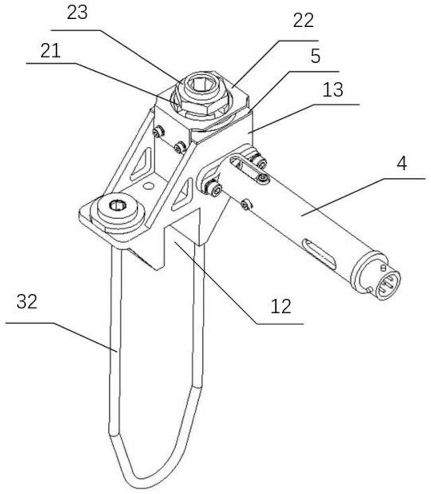
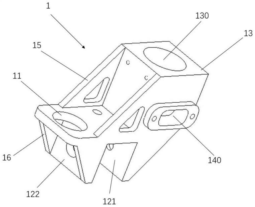
[0040] The present invention provides a binding unlocking device for spacecraft, which includes a base 1 , a tension cable assembly 2 , a locking assembly 3 and a fuse cutter 4 . The base 1 is used as an intermediate piece, on the one hand, it is installed on the spacecraft body through a corresponding structure, and on the other hand, the tension cable assembly 2, the locking assembly 3 and the fuse cutter 4 are connected and installed by setting corresponding connection holes and other structures. Specifically, the base 1 is designed as a seat structure, and the base 1 of the seat structure includes a seat board, a back board and a U-shaped slot 12 . The U-shaped slot 12 is located on the lower surface of the seat plate of the base 1, and serves as the outrigger structure of the seat, and is used for clamping connection with the corresponding structure of the spacecraft body. The U-shaped card slot 12 includes a first side plate 121 and a second side plate 122, the plate sur...

Embodiment 2

[0052] Embodiment 2 is formed on the basis of Embodiment 1. By optimizing the structure of the base, specifically, through the arrangement of ribs, the mechanical strength of the base is improved. specifically:

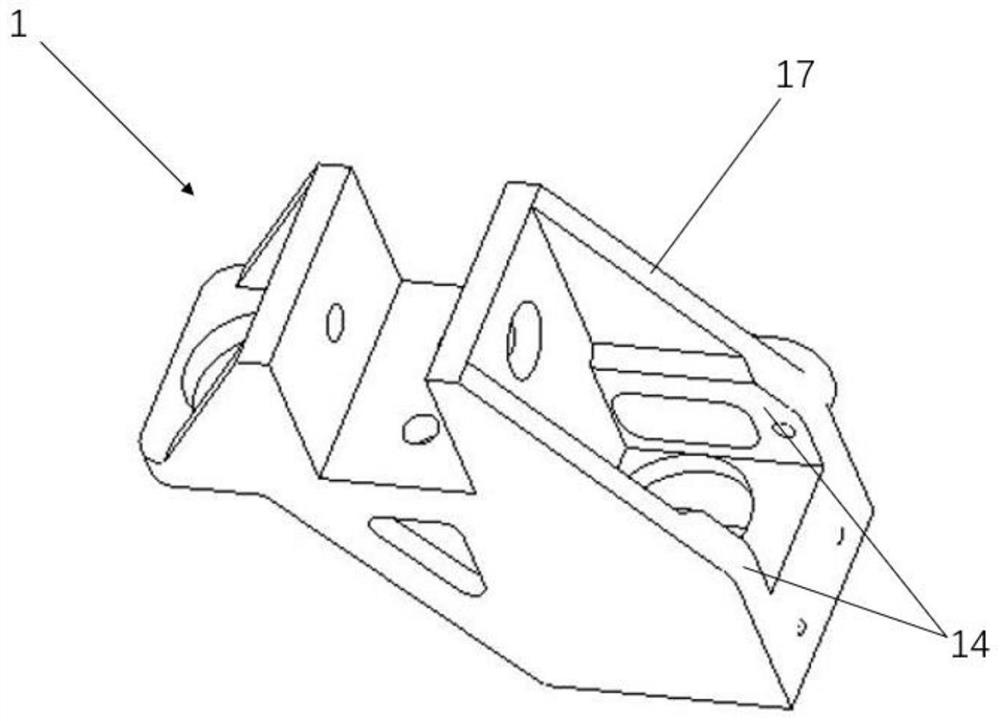
[0053] A first rib 15 is provided between the seat board of the base 1 and the back board of the base 1. The first ribs 15 are preferably two pieces arranged on both sides, preferably symmetrically arranged. The structural shape of the first rib 15 may be a triangular plate. Lightening holes can be provided in the first rib 15, and the lightening holes can be round holes or polygonal holes.

[0054] A second rib 16 is arranged between the wall plate 14 and the first side plate 121 of the U-shaped slot 12 . The number of the second ribs 16 is preferably two, and they are arranged on both sides of the first side plate 121 . The structural shape of the second rib 16 is preferably a triangular plate.

[0055] A third rib 17 is provided between the seat plate of the bas...


PUM


Abstract

The invention relates to a binding unlocking device for a spacecraft in the technical field of binding unlocking. The binding unlocking device comprises a base, a tension cable assembly, a locking assembly and a fusing type cutter. The base is of a seat type structure, a first connecting hole is formed in the end of a base seat plate, a U-shaped clamping groove is formed below the base seat plate,a connecting block is arranged on the back face of a base backrest plate, a stepped hole is formed in the connecting block, the side edge of the connecting block extends downwards to form a wall plate, and a second connecting hole is formed in the wall plate. The locking assembly comprises a rotating block and a U-shaped clamping sleeve, a threaded through hole is formed in the rotating block, the rotating block is rotationally installed in the stepped hole, and the U-shaped clamping sleeve is connected to the connecting block in a clamped mode and limits axial movement of the rotating block;the tension cable assembly comprises a fixed end, a fiber rod and a movable end which are connected in sequence, the fixed end is connected with the first connecting hole, and the movable end entersfrom the lower end of the stepped hole and then is in threaded connection with the threaded through hole; and the fusing type cutter fuses the fiber rod through the second connecting hole. The devicecan be repeatedly used, and is low in cost and good in economic benefit.

Description

technical field [0001] The invention relates to a binding unlocking device, in particular to a binding unlocking device for a spacecraft. Background technique [0002] At present, the pyrotechnic unlocking devices (such as explosive bolts, pyrotechnic cutters, etc.) commonly used in China are all linear compression, which realizes the compression of the separated parts and the body through threads or compression rods. Moreover, the instantaneous large-scale impact load generated by the pyrotechnic unlocking device will affect the attitude of the satellite and the sensitive stand-alone machine. The pyrotechnic device will produce corrosive and polluting gases during the ignition process, and there is a certain degree of safety in directly using the energy generated by the explosive explosion. Hidden dangers, pyrotechnic devices are dangerous goods, which brings inconvenience to ground storage and use, and the cost of ground tests increases due to the non-reusable characterist...

Claims


Application Information

Patent Timeline
Patent Type & Authority Applications(China)
IPC IPC(8): B64G1/64
CPCB64G1/64
Inventor 聂斌斌王萌赵发刚郑志刚顾志悦
Owner SHANGHAI SATELLITE ENG INST
Why Eureka
Try Eureka