Building elevator

A hoist and building technology, applied in the direction of cranes, shafts and bearings, etc., can solve the problems of insufficient technology and reduce the service life of steel wire ropes, and achieve the effects of avoiding frictional heat generation damage, reducing contact area, and reducing thermal friction

Inactive Publication Date: 2021-03-09
王云娥
View PDF0 Cites 1 Cited by
  • Summary
  • Abstract
  • Description
  • Claims
  • Application Information

AI Technical Summary

Problems solved by technology

Broadly speaking, elevators, cranes, winches, stabilizers, cranes, hoists, etc. can all be called hoists, and the transportation process is completed by dragging the flexible steel wire rope and the transported goods up and down by power machinery. An indispensable important part of heavy machinery, and the existing construction hoists that use steel wire ropes for lifting are not perfect in technology. The area is large, and the friction will generate heat, so the thermal friction area is large, which is easy to increase the wear of the wire rope, thereby reducing the service life of the wire rope

Method used


Image

  • Building elevator
  • Building elevator
  • Building elevator

Examples


Embodiment 1

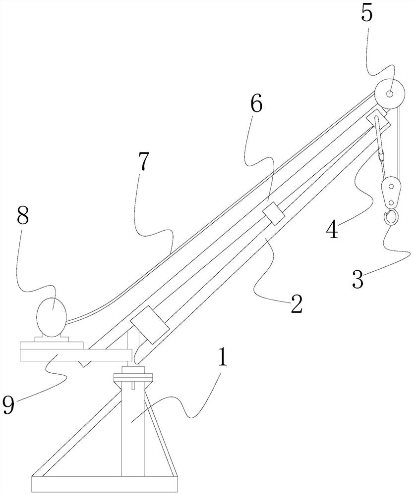
[0028] See Figure 1-5 The present invention provides a technical solution for a building hoist: its structure includes a rotating support table 1, a line 1 link 2, a sliding hook 3, a hook 4, a guide wheel 5, a line 6, a wire rope 7, and improvement The device 8, the support plate 9, the rotating support table 1 fixedly connected to a line 1 link 2, a second link 6, and the line No. 1 link 2 is located below the second link 6 and the outer side is connected by a connecting plate. Together, the top of the second link 6 is attached, and the rotating support table 1 is vertically connected to one end of the guide wheel 5, and the support plate 9 is mechanically connected to the lifting device 8, The lifting device 8 is connected to one end of the wire rope 7, and the other end of the wire rope 7 is coupled to the hook 4 through the guide wheel 5.

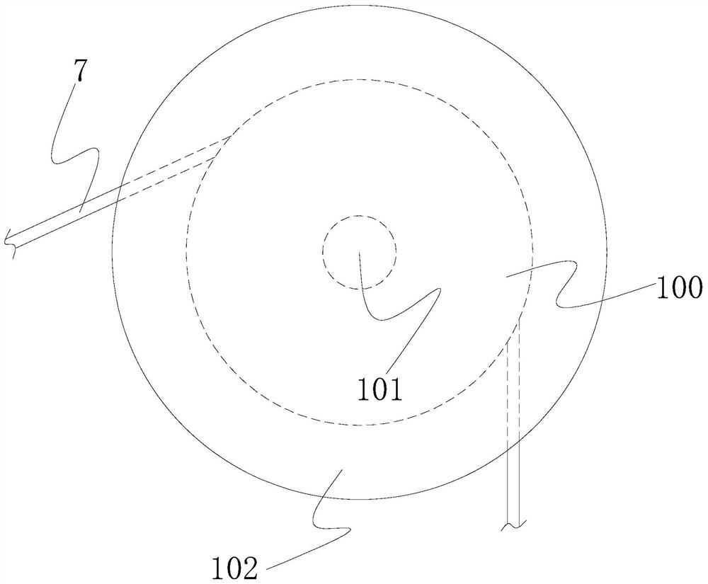
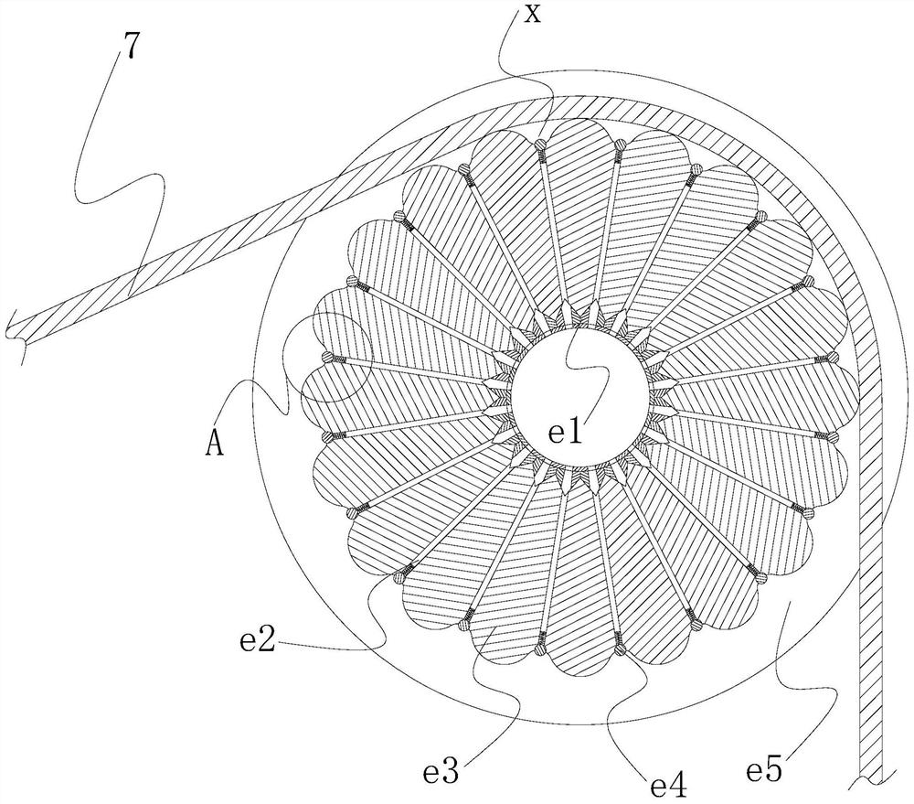
[0029] The guide wheel 5 includes a wheel 100, a rotating shaft 101, a heat sink 102, and the rotating shaft 101 runs through the wheel ...

Embodiment 2

[0038] See Figure 1-7 The present invention provides a technical solution for a building hoist: its structure includes a rotating support table 1, a line 1 link 2, a sliding hook 3, a hook 4, a guide wheel 5, a line 6, a wire rope 7, and improvement The device 8, the support plate 9, the rotating support table 1 fixedly connected to a line 1 link 2, a second link 6, and the line No. 1 link 2 is located below the second link 6 and the outer side is connected by a connecting plate. Together, the top of the second link 6 is attached, and the rotating support table 1 is vertically connected to one end of the guide wheel 5, and the support plate 9 is mechanically connected to the lifting device 8, The lifting device 8 is connected to one end of the wire rope 7, and the other end of the wire rope 7 is coupled to the hook 4 through the guide wheel 5.

[0039] The guide wheel 5 includes a wheel 100, a rotating shaft 101, a heat sink 102, and the rotating shaft 101 runs through the wheel b...


PUM


Abstract

The invention discloses a building elevator which structurally comprises a rotary supporting table, a first connecting rod, a sliding lifting hook, a pothook, a guide wheel, a second connecting rod, asteel wire rope, a lifting device and a supporting plate, and the first connecting rod and the second connecting rod are fixedly connected to the rotary supporting table. Compared with the prior art,the building elevator has the beneficial effects that a guide wheel of an existing building elevator is improved, the contact area of the steel wire rope and the guide wheel can be greatly reduced onthe basis that the stability of guide supporting is guaranteed, heat friction can be greatly reduced accordingly, the steel wire rope slides to drive a rotating shaft to slowly rotate, and thereforea circular rings are linked; and based on vertically downward gravity, a gravity block can provide power for displacement of a piston head, intermittent gas discharging is achieved, discharged gas cancool and dissipate heat of the steel wire rope, the abrasion degree of the steel wire rope is further reduced, and therefore the service life of the steel wire rope can be prolonged.

Description

Technical field [0001] The present invention relates to the field of construction machinery, in particular to a building hoist. Background technique [0002] The hoist is a large machinery device such as a mine hoist, a dam hoist, and the like by changing the potential energy. Generally, elevators, cars, rollers, escalates can be called hoist, and the wire rope is completed by power mechanical dragging flexible steel wire rope and transported goods. An important part of heavy machinery, and the existing building hoist in the existing wire rope is not perfect due to insufficient technology, and the wire rope is in contact with the guide wheel during the improvement of the wind, and the wire rope is in contact with the guide wheel. The area is large, and the friction is heat, the heat friction is large, and the wear of the wire rope is easily improved, thereby reducing the service life of the wire rope. Inventive content [0003] The main object of the present invention is to over...

Claims


Application Information

Patent Timeline
Patent Type & Authority Applications(China)
IPC IPC(8): B66C23/16B66C23/62F16C13/00
CPCB66C23/166B66C23/62F16C13/00
Inventor 王云娥
Owner 王云娥
Why Eureka
Try Eureka