
Pressure control type rotary type canning equipment

A rotary and canned technology, applied in packaging, liquid bottling, transportation and packaging, etc., can solve the problems affecting the quality of canning, poor fluidity, uneven canning, etc., to reduce the amount of foam generated, Avoid uneven, even canned results

Pending Publication Date: 2021-03-09
SUZHOU HENGYIHUI TECH CO LTD
View PDF0 Cites 2 Cited by
  • Summary
  • Abstract
  • Description
  • Claims
  • Application Information

AI Technical Summary

Problems solved by technology

[0003] In the canning process of beverages with poor fluidity and high viscosity, the liquid level often reaches the bottle mouth due to poor fluidity, and the liquid in the beverage bottle is not evenly distributed, and cavities are easy to form Such phenomena greatly affect the quality of canning, making the canning extremely uneven. For example: milk-type beverages, their polymer structure, and high air pressure in the bottle are often easy to concentrate, which is easy to cause, beverage bottles If the liquid level in the bottle is too low, it will affect the appearance of the product. On the contrary, if the air pressure in the bottle is too low, it is easy to form a cavity, and too many air bubbles in the bottle will cause imperfections such as overfilling and overflow. Therefore, for milk with higher viscosity , honey drinks, the present invention discloses a pressure-controlling rotary canning equipment that can flexibly control the air pressure in the bottle and has a more perfect canning process

Method used


Image

  • Pressure control type rotary type canning equipment
  • Pressure control type rotary type canning equipment
  • Pressure control type rotary type canning equipment

Examples


Embodiment Construction

[0035] The present invention will be described in detail below in conjunction with the implementations shown in the drawings, but it should be noted that these implementations are not limitations of the present invention, and those of ordinary skill in the art based on the functions, methods, or structural changes made by these implementations Equivalent transformations or substitutions all fall within the protection scope of the present invention.

[0036] It should be noted that, in the case of no conflict, the embodiments in the present application and the features in the embodiments can be combined with each other.

[0037] In the description of the present application, it should be understood that the terms "center", "longitudinal", "transverse", "upper", "lower", "front", "rear", "left", "right", " The orientation or positional relationship indicated by "vertical", "horizontal", "top", "bottom", "inner", "outer", etc. is based on the orientation or positional relationshi...


PUM


Abstract

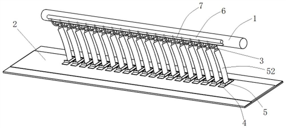
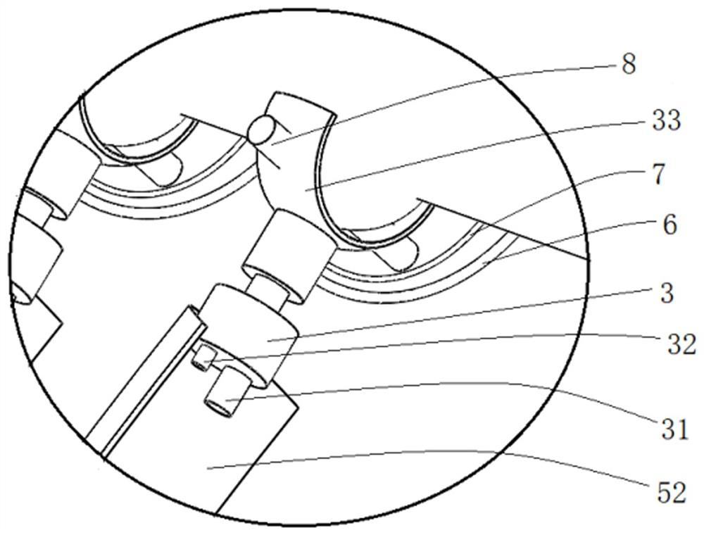
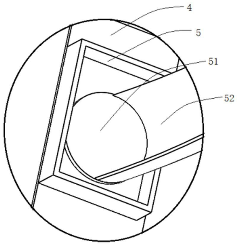
The invention provides pressure control type rotary type canning equipment. The pressure control type rotary type canning equipment comprises a transverse rod and a conveying belt arranged below the transverse rod, the transverse rod can horizontally ascend and descend and transversely move at the same time, a plurality of canning heads are distributed at the bottom end of the transverse rod at intervals, the canning heads are rotationally connected with the transverse rod, the situation that the canning heads rotate in the movement direction of the transverse rod and the canning heads rotatearound themselves are included, a plurality of fixing plates are arranged on the conveying belt, rotating brackets are arranged on the fixing plates and used for containing beverage bottles, rotatingdiscs are arranged in the rotating brackets and rotationally connected with the rotating brackets, one end of the periphery of each rotating disc extends in the direction of bottle openings of the beverage bottles to form a supporting arm, the supporting arms are fixedly connected with the canning heads, and one side of the bottom wall of each rotating bracket is rotationally connected with the fixing plates. According to the pressure control type rotary type canning equipment, the phenomena of over-shrinkage, over-expansion, cavity and the like in canning can be avoided, and pressure controland accurate high-quality canning are realized.

Description

technical field [0001] The invention relates to the technical field of beverage production, and more specifically relates to a pressure-controlling rotary canning equipment. Background technique [0002] The beverage industry is an emerging industry developed after the reform and opening up. It was listed as a national planned management product in 1982. The total output of beverages in the country was 400,000 tons. It is one of the key industries of the food industry that can better adapt to the needs of the market. The rapid development of the beverage industry has made due contributions to the construction of the national economy and the improvement of people's quality of life. Beverages have become an indispensable consumer food in people's daily life. . [0003] In the canning process of beverages with poor fluidity and high viscosity, the liquid level often reaches the bottle mouth due to poor fluidity, and the liquid in the beverage bottle is not evenly distributed, ...

Claims


Application Information

Patent Timeline
Patent Type & Authority Applications(China)
IPC IPC(8): B67C3/26B67C3/24
CPCB67C3/26B67C3/24B67C2003/2671B67C2003/2668B67C2003/2657
Inventor 周梦见
Owner SUZHOU HENGYIHUI TECH CO LTD
Learn More