
injector and engine

An injector and injection cavity technology, which is applied in the directions of machines/engines, engine components, fuel injection devices, etc., can solve the problems of slow response speed of gas fuel or liquid fuel injection, low control accuracy of injection opening and duration, etc. The effect of eliminating the control oil rail, eliminating the control oil circuit and related auxiliary control components, and short opening delay

Active Publication Date: 2022-02-22
FAW JIEFANG AUTOMOTIVE CO
View PDF0 Cites 0 Cited by
  • Summary
  • Abstract
  • Description
  • Claims
  • Application Information

AI Technical Summary

Problems solved by technology

[0003] In existing dual-fuel injectors, the injection response speed of gaseous fuel or liquid fuel is slow, and the control accuracy of injection opening and duration is low

Method used


Image

  • injector and engine
  • injector and engine
  • injector and engine

Examples


Embodiment Construction

[0040] In order to make the technical problems solved by the present invention, the technical solutions adopted and the technical effects achieved clearer, the technical solutions of the embodiments of the present invention will be further described in detail below in conjunction with the accompanying drawings. Obviously, the described embodiments are only the technical solutions of the present invention. Some, but not all, embodiments. Based on the embodiments of the present invention, all other embodiments obtained by those skilled in the art without making creative efforts belong to the protection scope of the present invention.

[0041] In the description of the present invention, it should be noted that the terms "center", "upper", "lower", "left", "right", "vertical", "horizontal", "inner", "outer" etc. The indicated orientation or positional relationship is based on the orientation or positional relationship shown in the drawings, and is only for the convenience of desc...


PUM


Abstract

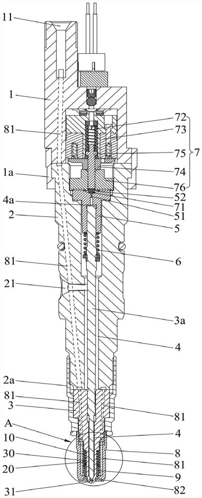
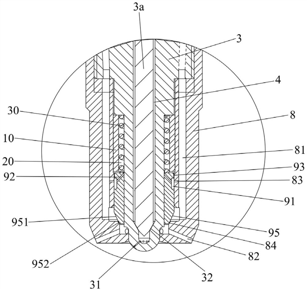
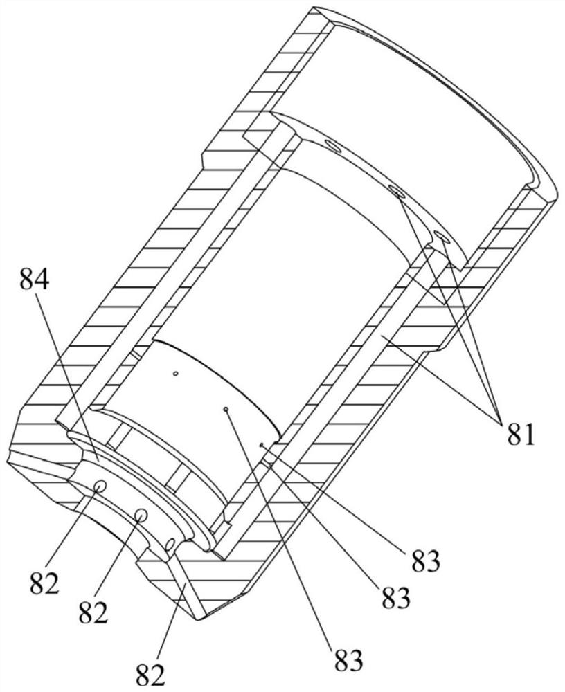
The invention relates to the field of internal combustion engines, and discloses an injector and an engine, comprising an injector body, a first injection port is opened at the injection end; a needle valve is penetrated in the injector body, and a first injection cavity is formed between the two The valve assembly is used to change the pressure of the control fluid in the first control chamber to cause the needle valve to move to communicate or cut off the first injection chamber and the first injection port; the nozzle sleeve is sleeved outside the injection end of the injector body, and the nozzle The sleeve is provided with a second injection chamber and a second injection port; the valve sleeve is sleeved on the injector body; the second control chamber is associated with the valve sleeve to cause the valve sleeve to move to cut off the second injection chamber and the second injection port; The first electromagnet is located in the second control chamber, and the first electromagnet is associated with the valve sleeve to cause the valve sleeve to move to communicate with the second injection chamber and the second injection port. The first electromagnet directly controls the opening and closing of the valve sleeve. Closed, the electromagnetic response is fast, the opening delay of the injector is short, and the injection duration control is more precise.

Description

technical field [0001] The invention relates to the field of internal combustion engines, in particular to an injector and an engine. Background technique [0002] Existing injectors generally include gaseous fuel injectors, liquid fuel injectors and dual fuel (gas fuel and liquid fuel) injectors. The gaseous fuel injector and the liquid fuel injector can only realize the injection of a single type of fuel, and cannot realize the simultaneous or optional injection of the gaseous fuel and the liquid fuel. The dual-fuel injector injects a small amount of liquid fuel into the cylinder in advance to ignite the gaseous fuel injected into the cylinder. The liquid fuel is injected at low pressure and is only used for ignition. The gaseous fuel is the main energy source of the engine. [0003] In the existing dual-fuel injector, the injection response speed of gaseous fuel or liquid fuel is relatively slow, and the control precision for the opening and duration of injection is low....

Claims


Application Information

Patent Timeline
Patent Type & Authority Patents(China)
IPC IPC(8): F02M61/18F02M63/00
CPCF02M61/1806F02M63/0017
Inventor 杨中伟高广新杨振国朱明健吴东兴张礼林张建刚夏少华宋国民黄成海
Owner FAW JIEFANG AUTOMOTIVE CO
Learn More