
Shell assembly of cooling-heating fan and cooling-heating fan

A technology for cooling and heating fans and housing components, which is applied to the components of pumping devices for elastic fluids, pump components, liquid fuel engines, etc. The effect of air intake area, improving air intake efficiency, improving air volume and air intake efficiency

Pending Publication Date: 2021-03-09
GREE ELECTRIC APPLIANCES INC
View PDF0 Cites 1 Cited by
  • Summary
  • Abstract
  • Description
  • Claims
  • Application Information

AI Technical Summary

Problems solved by technology

[0003] Therefore, the technical problem to be solved by the present invention is to overcome the defects that the filter screen of the cooling and heating fan in the prior art will cause the air inlet of the air inlet in the cold wind mode to be small and the air inlet efficiency is low, thereby providing a method that can improve the air inlet in the cold wind mode. The housing assembly of the cooling and heating fan and the cooling and heating fan with the highest air volume and air intake efficiency

Method used


Image

  • Shell assembly of cooling-heating fan and cooling-heating fan
  • Shell assembly of cooling-heating fan and cooling-heating fan
  • Shell assembly of cooling-heating fan and cooling-heating fan

Examples


Embodiment Construction

[0044] The technical solutions of the present invention will be clearly and completely described below in conjunction with the accompanying drawings. Apparently, the described embodiments are some of the embodiments of the present invention, but not all of them. Based on the embodiments of the present invention, all other embodiments obtained by persons of ordinary skill in the art without making creative efforts belong to the protection scope of the present invention.

[0045] In addition, the technical features involved in the different embodiments of the present invention described below may be combined with each other as long as there is no conflict with each other.

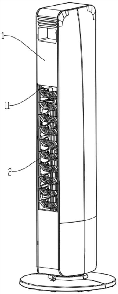
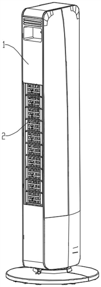
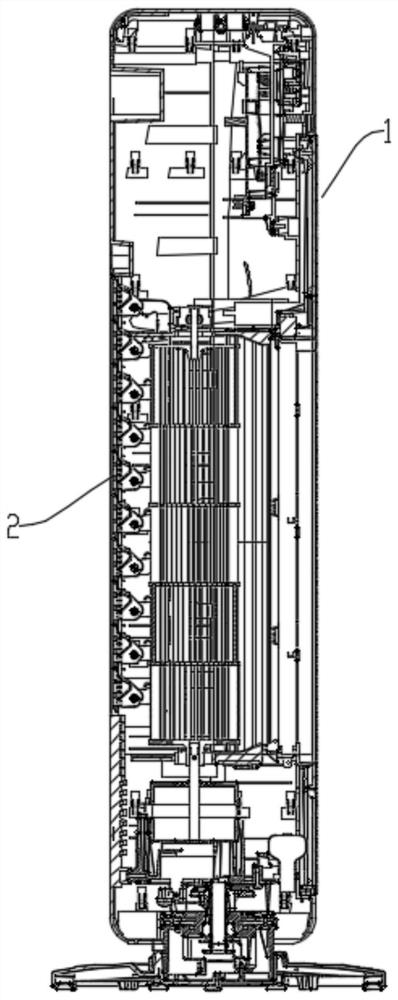
[0046] Such as Figure 1-Figure 17 As shown, this embodiment provides a housing assembly of a cooling and heating fan, including a housing 1 , a filter 21 assembly and at least one switching structure.

[0047] The casing 1 is provided with an air inlet 11 .

[0048] The filter 21 assembly is arranged at th...


PUM


Abstract

The invention provides a shell assembly of a cooling-heating fan and the cooling-heating fan. The shell assembly of the cooling-heating fan comprises a shell provided with an air inlet, a filter screen assembly and at least one switching structure. The filter screen assembly is arranged at the air inlet and comprises multiple filter units which are rotatably connected to the shell, and filter screens are arranged on the filter units. The at least one switching structure is connected with the filter units and is provided with a first position for enabling the filter units to cover the air inletand a second position for enabling the filter units to open the air inlet under the action of external force. According to the shell assembly, by arranging the filter screens, the situation that dustenters a machine body and is bonded to a heating body to reduce the heating efficiency in the warm air manner can be avoided, and the air volume and the air inlet efficiency of the air inlet in the cold air manner can be improved.

Description

technical field [0001] The invention relates to the technical field of household appliances, in particular to a housing assembly of a cooling and heating fan and the cooling and heating fan. Background technique [0002] After the cooling and heating fan is used for a long time, the dust in the air will stick to the heating element and reduce the heating efficiency. For this reason, present heating and cooling fan usually can be provided with filter screen at air inlet, filters the dust in the air, to prevent dust from adhering on the heating element. However, most of the existing cooling and heating fans are directly placed with a filter screen at the air inlet. In different cooling and heating modes, the incoming air needs to pass through the filter screen, which will result in a small air volume and low air intake efficiency at the air inlet under the cooling mode. Contents of the invention [0003] Therefore, the technical problem to be solved by the present invention...

Claims


Application Information

Patent Timeline
IPC IPC(8): F04D29/40F04D29/70F04D25/08
CPCF04D25/08F04D29/403F04D29/701
Inventor 徐余良刘哲赵文杰董情
Owner GREE ELECTRIC APPLIANCES INC
Learn More