Gas self-closing valve of central control room

A gas self-closing valve and centralized control room technology, which is applied in the direction of valve lift, valve details, valve devices, etc., can solve the problems of hidden safety hazards, large loss of transmission force, and inability to automatically close effectively, so as to achieve timely closure and safety protection good effect

Active Publication Date: 2021-03-09
品风燃气安全技术(广东)有限公司
View PDF5 Cites 2 Cited by
  • Summary
  • Abstract
  • Description
  • Claims
  • Application Information

AI Technical Summary

Problems solved by technology

[0004] However, the transmission of the force of the existing domestic gas safety self-closing valve is changed from the upper and lower force to the lateral force, which makes the relationship between the horizontal pull shaft and its limit structure, the rotation structure between the horizontal pull shaft and the vertical pull shaft due to Adherence of impurities such as dust and tar in the gas pipeline leads to the jamming of the transmission structure, which makes it impossible to automatically shut down effectively when the gas supply pressure is abnormal, and the loss of the force transmission force of each structural part is large, and it is easy to be damaged in the gas pipeline. When the supply is abnormal, it cannot achieve self-closing in a stable and timely manner, which may easily cause safety hazards

Method used


Image

  • Gas self-closing valve of central control room
  • Gas self-closing valve of central control room
  • Gas self-closing valve of central control room

Examples


Embodiment Construction

[0024] The technical solutions in the embodiments of the present invention will be clearly and completely described below in conjunction with the accompanying drawings in the embodiments of the present invention. Apparently, the described embodiments are only some of the embodiments of the present invention, not all of them. Based on the embodiments of the present invention, all other embodiments obtained by persons of ordinary skill in the art without making creative efforts all belong to the protection scope of the present invention.

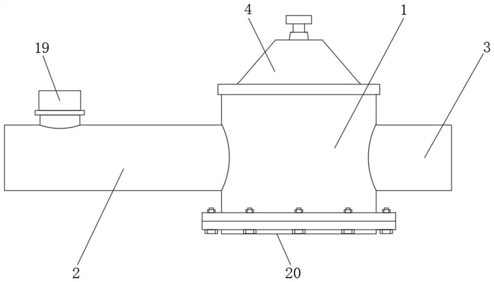
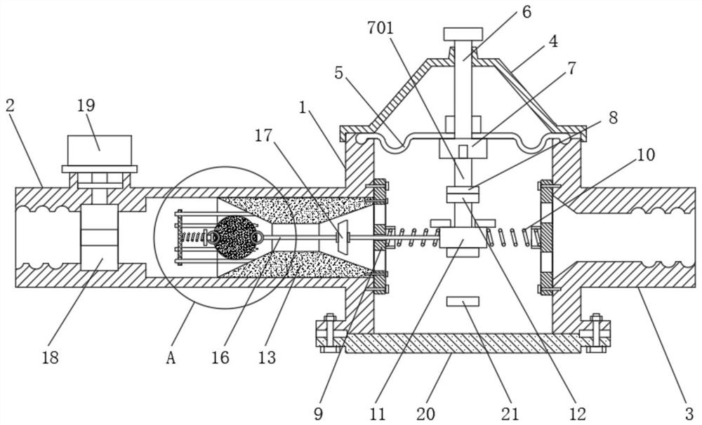
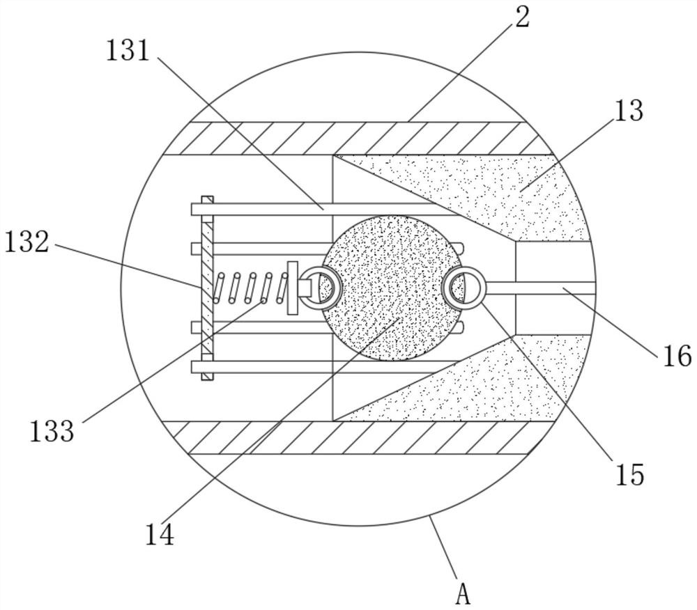
[0025] see Figure 1-6 , a gas self-closing valve in a centralized control room, including a valve housing 1, the two sides of the valve housing 1 are respectively provided with an intake pipe 2 and an air guide pipe 3, the top of the valve housing 1 is fixedly fitted with an upper cover 4, and the inner cavity of the valve housing 1 The top of the diaphragm 5 is provided with a diaphragm 5 in the state, the middle part of the diaphragm 5 is f...


PUM


Abstract

The invention relates to the field of domestic gas safety valves, and discloses a gas self-closing valve of a central control room. The gas self-closing valve comprises a valve casing, and a gas inletpipe and a gas guide pipe are arranged on the two sides of the valve casing separately; an upper sealing cover is fixedly arranged on the top of the valve casing in a sleeving mode, and a diaphragm in a state is arranged on the top of an inner cavity of the valve casing; a linkage shaft is fixedly arranged in the middle of the diaphragm in the sleeving mode; and the bottom end of the linkage shaft is fixedly connected with a limit sealing plate located below the membrane. According to the gas safety valve of the central control chamber, through the structural design that the inner diameters of the two sides of a valve seat in the gas inlet pipe are evenly reduced from outside to inside, and by means of the mode that a valve ball and the linkage block are connected through a steel wire, onthe premise of achieving the safe self-closing effect in case of abnormal gas supply pressure, an existing transmission mode is replaced by the valve seat and the valve ball; force conduction is effectively reduced, and up-down stress is converted into transverse stress; and thus, it is guaranteed that the gas safety valve can be stably closed in time in case of overpressure and low-pressure of gas supply, so that the good safety protection effect of the gas safety valve is guaranteed.

Description

technical field [0001] The invention relates to the field of household gas safety valves, in particular to a gas self-closing valve for a centralized control room. Background technique [0002] With the development of people's life, green energy such as natural gas has also been popularized. More and more families use natural gas. Since natural gas and other gases are flammable and explosive, safety protection measures are also extremely important while using gas. A gas safety valve needs to be installed at the end of the pipeline so that when the gas supply is abnormal, it will be automatically closed for safety protection. [0003] The existing gas safety valve is also called gas self-closing valve. There is an elastic diaphragm inside the gas self-closing valve. Using the pressure of the gas supply and the suction force of the magnet, the elastic diaphragm is in a flat equilibrium state. When overpressure occurs , undervoltage or overcurrent, the elastic diaphragm bounce...

Claims


Application Information

Patent Timeline
IPC IPC(8): F16K31/365F16K1/14F16K1/32F16K27/02
CPCF16K1/14F16K1/32F16K27/0245F16K31/365
Inventor 李俊德张见宗
Owner 品风燃气安全技术(广东)有限公司
Why Eureka
Try Eureka