
Medium heating device for testing military parts

A technology for medium heating and components, applied in heat storage heaters, fluid heaters, lighting and heating equipment, etc., can solve the problems of volume and cost increase, low work efficiency, polluted medium, etc., and achieve volume and cost reduction , Avoid temperature instability and increase heat transfer efficiency

Inactive Publication Date: 2021-03-09
YANGZHOU YOKI ELECTRIC
View PDF3 Cites 0 Cited by
  • Summary
  • Abstract
  • Description
  • Claims
  • Application Information

AI Technical Summary

Problems solved by technology

[0004] In view of the above situation, in order to overcome the defects of the prior art, the present invention provides a medium heating device for military parts testing, which solves the problem that the outlet medium of the existing medium heating device wants to reach a stable temperature, usually the pressure of the medium is stable, and the flow rate is stable , the outlet temperature of the heater will be stable, but it is not applicable to the situation where the working conditions change frequently and randomly, and the stable outlet temperature cannot be obtained under the same circumstances, and it takes a long time to heat to the required temperature, which makes the work efficiency low. At the same time The use of direct heating will pollute the medium, and the use of a small number of main pipes will result in low heat exchange efficiency and large pipe sizes, which will increase the volume and cost.

Method used


Image

  • Medium heating device for testing military parts
  • Medium heating device for testing military parts
  • Medium heating device for testing military parts

Examples


Embodiment Construction

[0018] By the following Figure 1-4 Detailed description of the specific embodiments of the present invention will be described in detail.

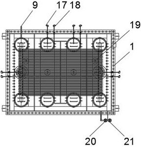
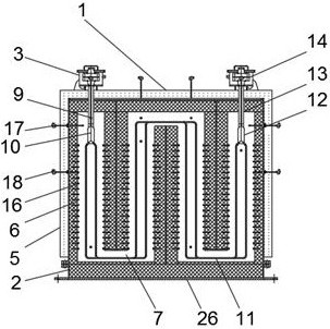
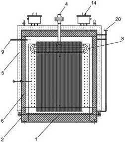
[0019] Embodiment figure 1 , figure 2 , image 3 with Figure 4 It is given, the present invention includes a furnace body 1, an outer side of the furnace body 1 is provided, and the inside of the furnace body housing 2 is provided with a heating chamber 7, and one side of the top end of the furnace body 1 is provided with a first junction box 3, a furnace a central top body 4 is provided with a medium inlet, a medium inlet of the first terminal box 4 through the bottom end 3 of the furnace body 1 is connected to a first air manifold 8, 7 at a position corresponding to the upper heating chamber of the furnace body 1 is provided with a protective gas inlet 9. The other end of the heating chamber 7 is provided with a protective gas outlet 20. The bottom end of the first total air tube 8 is connected to the branch pipe 11, and the branch tube 1...


PUM


Abstract

The invention discloses a medium heating device for testing military parts. The medium heating device comprises a furnace body; a furnace body shell is arranged outside the furnace body; a heating cavity is formed inside the furnace body shell; a first junction box is arranged on one side of the top end of the furnace body; a medium inlet is formed at the middle part of the top end of the furnacebody; the bottom end of the medium inlet penetrates through the furnace body to be connected with a first air header pipe; a shielding gas inlet is formed at the position, corresponding to the heatingcavity, at the upper portion of the furnace body; a shielding gas outlet is formed at the other end of the heating cavity; the bottom end of the first air header pipe is connected with a branch pipe;and the branch pipe is positioned inside the heating cavity. According to the invention, indirect heating is adopted, so that a medium is not polluted; a main pipeline is changed into a plurality ofbranch pipelines, so that the heat exchange efficiency is effectively improved, and the pipeline size is reduced, so that both the volume and the cost are reduced; and a large hot melting structure isadopted, and stored energy can be released at any time, so that the situation that the temperature is unstable due to working condition switching every time is avoided.

Description

Technical field [0001] The present invention relates to the technical field of military components, in particular, involving a medium heating device for military components test. Background technique [0002] Military workers are industrial in military. More military components in the military, in order to ensure the quality of military components, the military test platform is required to test parts, and some parts need to withstand gas impact under high temperature and high pressure. The performance of the product, which requires heating of the medium to the medium heating device. [0003] However, the existing medium heating device is exported to reach a stable temperature. The pressure of the general medium is stable, the flow is stable, and the exit temperature of the heater will be stable, but the situation is not applicable to the situation where the situation is frequent, it is not possible. Get a stable outlet temperature, and the length of time used to heat to the desir...

Claims


Application Information

Patent Timeline
IPC IPC(8): F24H7/02F24H9/00F24H9/18F24H9/20F24H9/02
CPCF24H7/0216F24H9/0052F24H9/02F24H9/1863F24H9/2071
Inventor 夏鑫姚小明许顺海
Owner YANGZHOU YOKI ELECTRIC
Learn More