Optical imaging lens, lens module and electronic equipment

An optical imaging lens and lens technology, which is applied in optics, optical components, instruments, etc., can solve the problems of inconvenient optical imaging system miniaturization, light and thin design, and increase the production cost of optical imaging system, so as to expand the field of view range, The effect of reducing sensitivity and slimming design

Active Publication Date: 2021-03-09
TIANJIN OFILM OPTO ELECTRONICS CO LTD
View PDF5 Cites 0 Cited by
  • Summary
  • Abstract
  • Description
  • Claims
  • Application Information

AI Technical Summary

Problems solved by technology

[0003] At present, in some designs, the imaging quality of the optical imaging system is improved by using the diffractive surface, and the addition of the diffractive surface increases the processing difficulty of the optical imaging system, increases the production cost of the optical imaging system, and is not convenient to realize the miniaturization of the optical imaging system Thin and lightweight design

Method used


Image

  • Optical imaging lens, lens module and electronic equipment
  • Optical imaging lens, lens module and electronic equipment
  • Optical imaging lens, lens module and electronic equipment

Examples


Embodiment 1

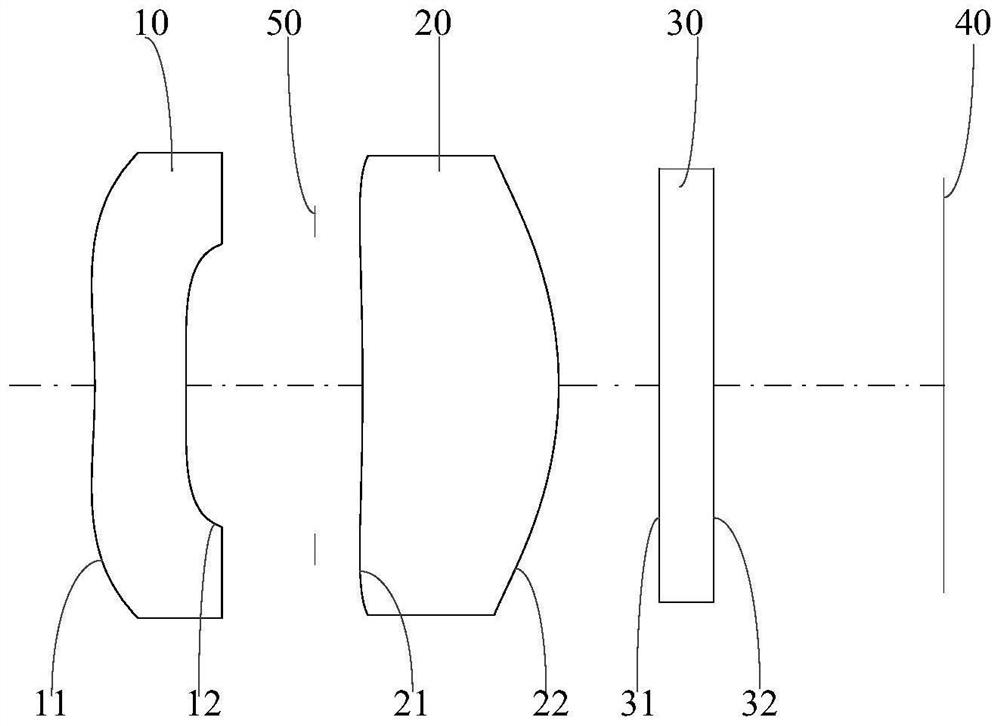
[0053] see figure 1 with figure 2 As shown, according to Embodiment 1 of the present invention, an optical imaging lens is provided, and the optical imaging lens includes a first lens 10, a diaphragm 50, a second lens 20 and a protective plate 30 arranged in sequence from the object side to the image side .

[0054] Wherein, the first lens 10 has negative refractive power, and the near optical axis region of the image side 11 of the first lens 10 is a concave surface, the near circumference region is a convex surface, and the near optical axis region of the object side 12 of the first lens 10 is a convex surface, The near-circumferential area is concave, and the image side 11 and the object side 12 of the first lens 10 are both aspherical;

[0055] The second lens 20 has a positive refractive power, and the near optical axis region of the image side 21 of the second lens 20 is a concave surface, and the near circumference region is a concave surface, and the near optical ax...

Embodiment 2

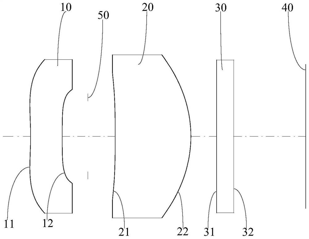
[0078] see image 3 with Figure 4 As shown, according to Embodiment 2 of the present invention, an optical imaging lens is provided. The structure of the optical imaging lens is the same as that in Embodiment 1. The difference is that the optical imaging lens in this embodiment satisfies the following conditional formula :

[0079] -13<(f1*f2) / (CT2-CT1)=-9.779<-8;

[0080] 3.5

[0081] 0.5mm

[0082] 2<2*Imgh / EPD=2.482<3;

[0083] 1.5

[0084] f / EPD=1.1<1.5;

[0085] -0.5

[0086] Wherein, the above-mentioned parameters have been defined before, and will not be repeated here, and the units of parameters f1, f2, CT1, CT2, TTL, f, Imgh, SAG_S22, and EPD are millimeters (mm), and the units of FOV are degrees (° ).

[0087] Table 1 is a table of characteristics of the optical imaging lens of this embodiment, wherein, the data of the focal length is obtained by using infrared light with a...

Embodiment 3

[0096] see Figure 5 with Image 6 As shown, according to Embodiment 3 of the present invention, an optical imaging lens is provided. The structure of the optical imaging lens is the same as that in Embodiment 1. The difference is that the optical imaging lens in this embodiment satisfies the following conditional formula :

[0097] -13<(f1*f2) / (CT2-CT1)=-12.332<-8;

[0098] 3.5

[0099] 0.5mm

[0100] 2<2*Imgh / EPD=2.373<3;

[0101] 1.5

[0102] f / EPD=1.1<1.5;

[0103] -0.5

[0104] Wherein, the above-mentioned parameters have been defined before, and will not be repeated here, and the units of parameters f1, f2, CT1, CT2, TTL, f, Imgh, SAG_S22, and EPD are millimeters (mm), and the units of FOV are degrees (° ).

[0105] Table 5 is the characteristic table of the optical imaging lens of this embodiment, wherein, the data of the focal length is obtained by using infrared light with a...


PUM


Abstract

The invention relates to the technical field of camera devices, and particularly discloses an optical imaging lens, a lens module and electronic equipment. The optical imaging lens comprises a first lens and a second lens which are sequentially arranged from the object side to the image side, the first lens has negative refractive power, the second lens has positive refractive power, and the imageside surface of the second lens is a convex surface in a paraxial region; the optical imaging lens meets the conditional expression that -13 < (f1 * f2)/(CT2-CT1) < -8, f1 is the focal length of thefirst lens, f2 is the focal length of the second lens, CT1 is the center thickness of the first lens on the optical axis, and CT2 is the center thickness of the second lens on the optical axis. According to the optical imaging lens, on the premise that the optical performance requirement of the optical imaging lens is met, the optical imaging lens is more compact, and miniaturization, lightness and thinness design of the optical imaging lens can be achieved more conveniently.

Description

technical field [0001] The invention relates to the technical field of imaging devices, in particular to an optical imaging lens, a lens module and electronic equipment. Background technique [0002] At present, infrared thermometers are widely used in many public places (such as airports, railway stations, subway stations, large shopping malls, etc.). Generally, infrared thermometers regard the scene / person in the field of view as a hot spot for temperature measurement; The infrared imager records the relative value and distribution of the infrared radiation flux of the scene / person in the field of view, thereby forming the contrast of the infrared image; the infrared imaging thermometer measures the temperature distribution of the infrared image of the scene object, and uses the isotherm , false color, etc., so as to obtain an infrared image corresponding to the scene and including the temperature and its distribution. Infrared thermal imaging technology enables human bei...

Claims


Application Information

Patent Timeline
Patent Type & Authority Applications(China)
IPC IPC(8): G02B13/00G02B13/18
CPCG02B13/003G02B13/18
Inventor 乐宇明蔡雄宇董勇兵赵迪
Owner TIANJIN OFILM OPTO ELECTRONICS CO LTD
Why Eureka
Try Eureka