
Method, device, medium and computer equipment for initial value estimation of image points in a sub-region

A technique of seed area and sub-area, applied in the field of initial value estimation of image points in the sub-area

Active Publication Date: 2021-09-10
SEIZET TECH SHEN ZHEN CO LTD
View PDF9 Cites 0 Cited by
  • Summary
  • Abstract
  • Description
  • Claims
  • Application Information

AI Technical Summary

Problems solved by technology

[0008] The purpose of the present invention is to provide a method for initial value estimation of image points in a sub-area to solve the problems existing in the prior art, especially suitable for initial value estimation in scenarios such as continuous deformation, deformation process analysis requirements, and large deformation.

Method used


Image

  • Method, device, medium and computer equipment for initial value estimation of image points in a sub-region
  • Method, device, medium and computer equipment for initial value estimation of image points in a sub-region
  • Method, device, medium and computer equipment for initial value estimation of image points in a sub-region

Examples


Embodiment 1

[0075] Such as figure 1 As shown, the present invention discloses a method for estimating an initial value of an image point in a sub-region, comprising the following steps:

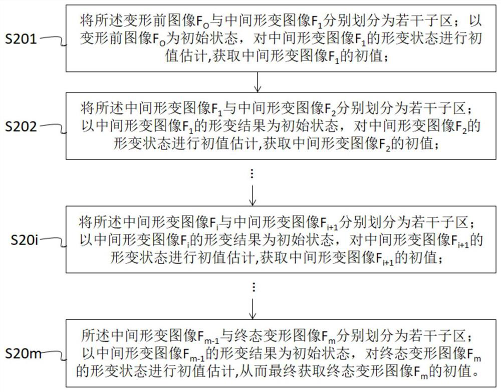
[0076] S1 acquires the image collection of the object under test, and divides the images in the image collection into multiple image pairs (F i , F i+1 ), where, 0≤ii is the current state image, F i+1 is the next state image, F O is the image before deformation, F m is the final deformed image;

[0077] S2 from the current state image to the pre-deformation image F O At first, according to the order of deformation occurrence, for each image pair (F i , F i+1 ) perform the following steps until the next state image is the final state deformation image F m :

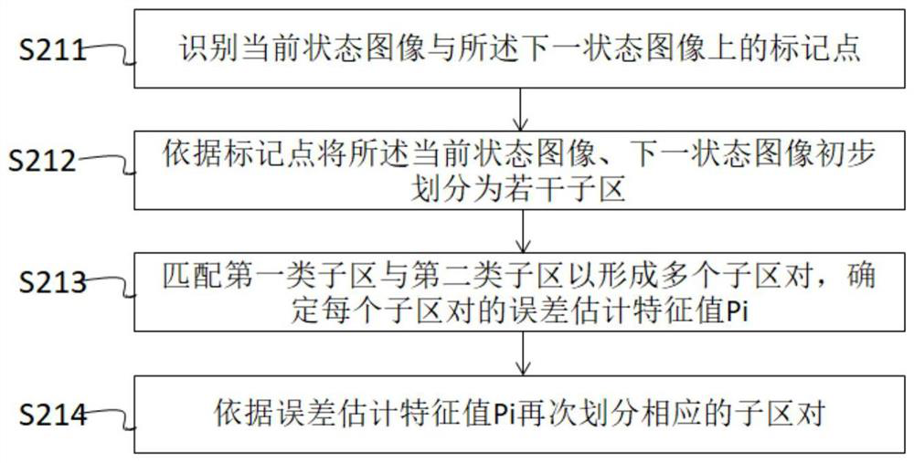
[0078] S21 each of the current state images F i with the next state image F i+1 respectively divided into several sub-areas, wherein the current state image F i The sub-area is the first type of sub-area, and the next state image F i+1 T...

Embodiment 2

[0154]Such as Figure 12 As shown, the present invention also discloses an initial image point estimation device 10 in a sub-region, including:

[0155] Image acquisition and pairing module 11 is used to obtain the image set of the test piece, and the images in the image set are divided into a plurality of image pairs (F i , F i+1 ), where, 0≤ii is the current state image, F i+1 is the next state image, F O is the image before deformation, F m is the final deformed image;

[0156] The initial value estimation module 12 is used to convert the image F from the current state image to the image F before deformation O At first, according to the order of deformation occurrence, for each image pair (F i , F i+1 ) perform the following steps until the next state image is the final state deformation image F m :

[0157] The sub-regions are divided into sub-modules, which are used to convert each of the current state images F i with the next state image F i+1 respectively div...

Embodiment 3

[0192] Figure 13 Shown is a schematic structural diagram of a computer device provided by an embodiment of the present invention, such as a smart phone, a tablet computer, a notebook computer, a desktop computer, a rack server, a blade server, a tower server or a cabinet server that can execute programs (including independent servers, or server clusters composed of multiple servers), etc. The computer device 20 of this embodiment at least includes but is not limited to: a memory 21 and a processor 22 that can communicate with each other through a system bus, such as Figure 13 shown. It should be pointed out that, Figure 13 Only computer device 20 is shown having components 21-22, but it should be understood that implementing all of the illustrated components is not a requirement and that more or fewer components may instead be implemented.

[0193] In this embodiment, the memory 21 (that is, a readable storage medium) includes a flash memory, a hard disk, a multimedia ca...


PUM


Abstract

The invention discloses a method, device, storage medium and computer equipment for estimating an initial value of an image point in a sub-area, comprising: acquiring an image set of a test piece, and dividing the images in the image set into a plurality of image pairs (F i , F i+1 ), where, 0≤i<m, F i is the current state image, F i+1 is the next state image, from the current state image to the pre-deformation image F O At first, according to the order of deformation occurrence, for each image pair (F i , F i+1 ) perform the following steps until the next state image is the final state deformation image F m : convert each current state image F i with the next state image F i+1 are divided into several sub-areas respectively, among which, the current state image F i The sub-area is the first type of sub-area, the next state image F i+1 The sub-area is the second type of sub-area; based on the sub-area division results, the current state image is used as the initial state to estimate the initial value of the next state image, which can quickly and accurately realize the initial value estimation of the image points in the sub-area, satisfying the continuous Deformation, analysis requirements for deformation process, and valuation requirements in large deformation scenarios.

Description

technical field [0001] The invention relates to speckle strain measurement technology, in particular to a method, device, medium and computer equipment for estimating an initial value of an image point in a sub-region. Background technique [0002] Three-dimensional digital image correlation technology (Three Digital Image Correlation, 3D-DIC), the three-dimensional speckle strain measurement method has many advantages such as non-contact, non-interference, high precision, three-dimensional modeling, and full-field measurement. , gradually expanded from traditional material mechanics measurement to many fields such as construction engineering, life science, aerospace, industrial testing and so on. [0003] For a long time, how to further improve the accuracy of speckle strain measurement, calculation speed, real-time measurement, and ensure the robustness of measurement results has always been a research hotspot. Aiming at the matching problem of the corresponding image poi...

Claims


Application Information

Patent Timeline
Patent Type & Authority Patents(China)
IPC IPC(8): G06T7/00G06T7/33G01B11/16
CPCG01B11/162G06T7/0002G06T2207/10004G06T2207/20021G06T7/33
Inventor 胡浩王康润
Owner SEIZET TECH SHEN ZHEN CO LTD
Learn More