Switch cabinet group

A switchgear and cabinet technology, applied in the direction of switchgear, switchgear setting, substation/switch layout details, etc., can solve the problems of main busbar error, difficult fixed connection, etc., and achieve simple tightening method, simple structure, Guaranteed flow effect

Active Publication Date: 2021-03-09
HENAN SENYUAN ELECTRIC CO LTD
View PDF22 Cites 0 Cited by
  • Summary
  • Abstract
  • Description
  • Claims
  • Application Information

AI Technical Summary

Problems solved by technology

[0004] The purpose of the present invention is to provide a switchgear group to solve the problem that the main busbar in the prior art has errors in foundation construction or processing errors in the two air chambers The technical problem of not being easy to fix the connection on two insulators

Method used


Image

  • Switch cabinet group
  • Switch cabinet group
  • Switch cabinet group

Examples


specific Embodiment

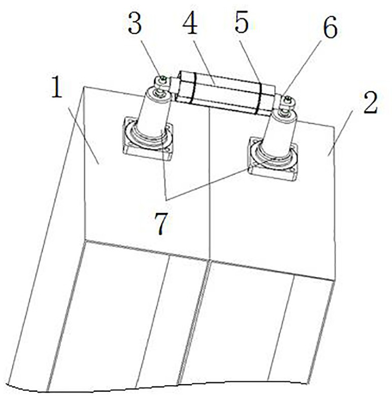
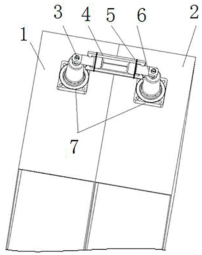
[0034] Such as figure 1 As shown, the switchgear group includes a left cabinet unit 1 and a right cabinet unit 2 arranged along the left and right directions. Insulators 7 are fixed on the top walls of the two cabinet units, and a conductive telescopic panel is provided between the two insulators 7. structure. In this embodiment, the conductive telescopic structure is a sleeve-type telescopic structure, which increases the conductive contact area and ensures the flow rate. Of course, in other embodiments, it may also be a guide groove telescopic structure.

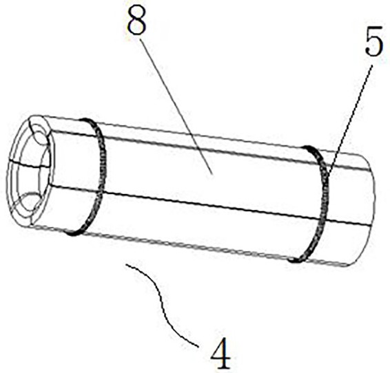
[0035] Such as figure 1 , figure 2 and Figure 4 As shown, the sleeve-type telescopic structure includes a conductive sleeve 4 and two conductive rods 6. The two conductive rods 6 are respectively located at both ends of the conductive sleeve 4 and are slidably fitted in the conductive sleeve 4. The conductive rod on the left side The left end of 6 is fixed on the insulator 7 of the left cabinet unit 1 through the fa...


PUM


Abstract

The invention relates to a switch cabinet group, and the switch cabinet group comprises at least two cabinet body units which are arranged side by side, and the top of each cabinet body unit is provided with an insulator; a conductive telescopic structure is arranged between the two insulators of any two adjacent cabinet body units, one end of the conductive telescopic structure is fixedly connected to one insulator, and the other end of the conductive telescopic structure is connected to the other insulator so as to adapt to the distance between the two insulators. By arranging the conductivetelescopic structure between the two insulators of the two adjacent cabinet body units, the distance between the two insulators can be adapted by stretching out and drawing back while the conductiveconnection of the two insulators is ensured, i.e., when an error occurs in on-site foundation construction or a processing error exists in the two cabinet body units, the actual cabinet combination size of the two cabinet body units is enabled to be consistent with the theoretical cabinet combination size through telescoping of the conductive telescoping structure so that the main bus is enabled to be more easily and fixedly connected to the two insulators.

Description

technical field [0001] The invention relates to a switch cabinet group. Background technique [0002] In the prior art, when the switchgears are combined, the bus bar connection is generally implemented on the side or top of the switchgears. For example, the Chinese utility model patent whose authorized announcement number is CN204156398U discloses a gas busbar structure, which includes a left air chamber and a right air chamber. Insulators are fixedly connected to the top walls of the left air chamber and the right air chamber. The lower parts of the two insulators Both are fixedly connected with copper bars, and the upper parts of the two insulators are connected through the main busbar to realize the communication of the copper bars in the left air chamber and the right air chamber. [0003] Since the two ends of the main busbar are fixedly connected to the two insulators, when there are errors in the foundation construction on site or processing errors in the two gas ch...

Claims


Application Information

Patent Timeline
Patent Type & Authority Applications(China)
IPC IPC(8): H02B13/035H02B1/30H01R4/30H01R4/48H01R4/60H01R11/01H01R11/09
CPCH02B13/035H02B1/308H01R11/09H01R11/01H01R4/60H01R4/48H01R4/30
Inventor 栗俊杰葛淑娜赵睿哲司贞员周航李浩田耿双双
Owner HENAN SENYUAN ELECTRIC CO LTD
Why Eureka
Try Eureka