Device for adjusting rotatble milling spindle of edge milling machine, and edge milling machine

A milling cutter bar, rotary technology, applied in milling machine equipment, machine tool parts, details of milling machine equipment, etc., to achieve the effect of improving reading accuracy, simple adjustment, and comfortable device operation

Pending Publication Date: 2021-03-09
麦太保有限公司
View PDF10 Cites 0 Cited by
  • Summary
  • Abstract
  • Description
  • Claims
  • Application Information

AI Technical Summary

Problems solved by technology

However, the movement of the adjusting ring can only be achieved by lifting the adj

Method used


Image

  • Device for adjusting rotatble milling spindle of edge milling machine, and edge milling machine
  • Device for adjusting rotatble milling spindle of edge milling machine, and edge milling machine
  • Device for adjusting rotatble milling spindle of edge milling machine, and edge milling machine

Examples


Embodiment Construction

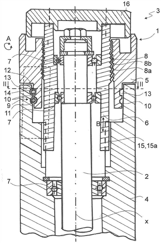
[0043] figure 1 A device 1 for adjusting a rotatable milling tool bar 2 of a milling machine 3 along the longitudinal axis x of the milling tool bar 2 is shown. The device 1 has, in particular, a body 4 , an actuating element 5 , which is rotatable according to arrow A, and an adjusting element 6 . To adjust the milling rod 2 , the adjusting element 6 acts on the milling rod 2 in the direction of the longitudinal axis x, so that a movement of the adjusting element 6 along the longitudinal axis x according to the arrow B causes a corresponding movement of the milling rod 2 . In the present case, the milling cutter bar 2 is mounted on the adjustment part 6 by means of a plurality of supports 7, so that the described coupling of the two components is ensured.

[0044]The operating member 5 is coupled to the adjusting member 6 such that a rotation of the operating member 5 about the longitudinal axis x according to arrow A causes the adjusting member 6 to move according to arrow ...


PUM


Abstract

The invention relates to a device (1) for adjusting a rotatable milling spindle (2) of an edge milling machine (3) along a longitudinal axis (x) of the milling spindle (2). The device comprises an adjustment element (6) which acts on the milling spindle in the direction of the longitudinal axis (x) in order to adjust the milling spindle (2); an actuation element (5), which is connected to the adjustment element (6) in such a way that rotation of the actuation element (5) causes translation of the adjustment element (6) in the direction of the longitudinal axis (x); a housing (4), with respectto which the actuation element (5) is rotatably mounted and to which the adjustment element (6) is at least indirectly connected in a rotationally fixed manner; a blocking apparatus (9), by means of which the actuation element (5) is fixed to the housing (4) in such a way that the actuation element cannot translate in the direction of the longitudinal axis (x); a fixing apparatus (12), by means ofwhich the rotatability of the actuation element (5) can at least be limited.

Description

technical field [0001] The invention relates to a device for adjusting a rotatable milling shank of an edge milling machine along the longitudinal axis of the milling shank and to an edge milling machine with a rotatable milling shank. Background technique [0002] An edge milling machine with such a device for adjusting the milling rod is known from EP 2535130 A2. By adjusting the milling tool shank along the longitudinal axis, ie adjusting its height, an optimum cutting depth can be achieved for machining edges and grooves, in particular in the case of metallic materials, for example for preparing welded edges. [0003] In the solution described in EP 2535130 A2, the adjusting ring is coupled via a wedge connection to the sleeve, which engages the internal thread of the milling machine body via an external thread. Thus, by turning the adjusting ring, the sleeve can be turned correspondingly, resulting in a translational movement along the longitudinal axis of the milling ...

Claims


Application Information

Patent Timeline
IPC IPC(8): B23C9/00B23C3/12B23Q16/00
CPCB23C9/00B23C2260/04B23C2260/84B23C2255/00B23C3/12B23Q16/008B23Q2220/006
Inventor 尼古拉·威尔曼苏珊·施米德贝格尔-布里内克
Owner 麦太保有限公司
Why Eureka
Try Eureka