
Equipment for removing defective sanitary napkins

A technology for sanitary napkins and defective products, which is applied in sorting and other directions, and can solve problems such as falling

Inactive Publication Date: 2021-03-12
广州畅新生物科技有限公司
View PDF0 Cites 0 Cited by
  • Summary
  • Abstract
  • Description
  • Claims
  • Application Information

AI Technical Summary

Problems solved by technology

[0003] Since the clamper on the sanitary napkin rejecting machine directly clamps the defective sanitary napkins upward, if the defective sanitary napkins are screened out because the edge sealing is not tight enough, it is easy to make the clamper not close enough to the sealing edge When the sanitary napkin is clamped, the plush cotton inside the sanitary napkin is squeezed out and falls on the surface of the qualified sanitary napkin, resulting in the need to remove the plush cotton on the surface of the qualified sanitary napkin

Method used


Image

  • Equipment for removing defective sanitary napkins
  • Equipment for removing defective sanitary napkins
  • Equipment for removing defective sanitary napkins

Examples


Embodiment 1

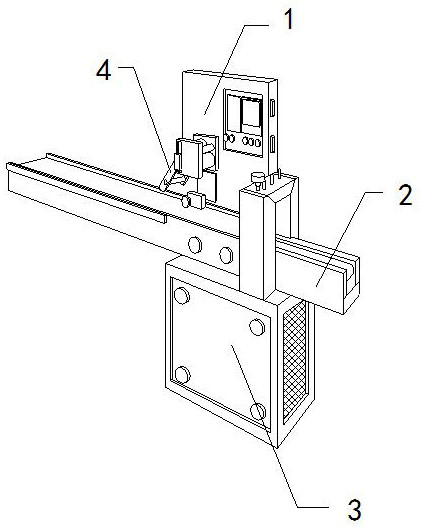
[0026] For example figure 1 -example Figure 5 Shown:

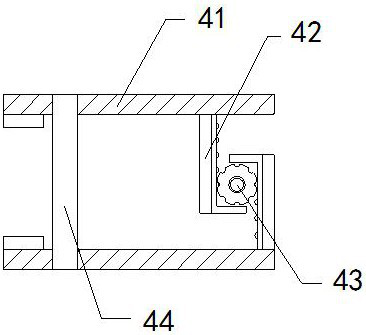
[0027] The present invention provides a device for rejecting defective sanitary napkins. At the upper end of the base 3, the holder 4 is movably engaged with the fixing plate 1; the holder 4 includes a clamping plate 41, a sliding plate 42, a transmission wheel 43, and a middle connecting rod 44. 42 is embedded and connected with the inner side of the clamping plate 41 , the transmission wheel 43 is engaged and connected between the two sliding plates 42 , and the middle connecting rod 44 is in clearance fit with the clamping plate 41 .

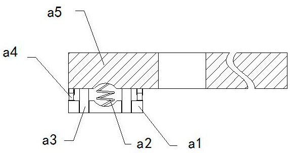
[0028] The clamping plate 41 includes a lower connecting plate a1, an elastic strip a2, a downward extending plate a3, a telescopic frame a4, and a plate body a5, and the lower connecting plate a1 is movably engaged with the bottom of the plate body a5 through the telescopic frame a4 , the elastic strip a2 is installed between the bottom of the plate body a5 and the upper surface of t...

Embodiment 2

[0034] For example Image 6 -example Figure 8 Shown:

[0035] The pressing block b2 includes a transition plate b21, an elastic rod b22, a contact plate b23, and an extension rod b24. The contact plate b23 is movably engaged with the transition plate b21 through the elastic rod b22. The upper end is fixedly connected with the bottom of the transition plate b21, and the transition plate b21 and the contact plate b23 are in clearance fit, and the contact plate b23 can be retracted upward under the fit of the elastic rod b22 through the reverse extrusion of the sanitary napkin on the contact plate b23. , so that the extension rod b24 can be extended downward along the contact plate b23.

[0036]The extension rod b24 includes a connecting plate c1, a resilient bar c2, a lower contact plate c3, and a combining rod c4. The resilient bar c2 is installed between the upper end of the inner wall of the connecting plate c1 and the combining bar c4. The lower contact plate c3 is embed...


PUM


Abstract

The invention discloses equipment for removing defective sanitary napkins. The equipment structurally comprises a fixed plate, a transfer table, a base and a holder, wherein the fixed plate is in embedded fixation and connection to the transfer table; the transfer table is mounted at the upper end of the base; and the holder is movably blocked with the fixed plate. Sides of the defective sanitarynapkins extrude a lower jointing plate, so that a lower extending plate can extend outwards along the lower jointing plate; sides of the defective sanitary napkins extrude a position between fasteningplates which can slide and expand outwards along a jointing rod, so that a pulling ring can pull the fastening plates to clamp the defective sanitary napkins. While the fastening plates are expanded,a contact plate without extrusion by a sanitary napkin tape can be pushed by an elastic rod to quickly return downwards, so that an extending-out rod can be quickly separated from the surface of thesanitary napkin tape, and thus, a lower contact plate can downwards extrude gas flow generated by shrinkage, and the sanitary napkin tape can be blown off.

Description

technical field [0001] The invention relates to the field of sanitary napkin equipment, in particular to a sanitary napkin rejecting defective product. Background technique [0002] The sanitary napkin rejecting machine is mainly used to screen and remove defective sanitary napkins. It can scan the defective sanitary napkins through intelligent identification, and then quickly remove the defective products through the gripper on the sanitary napkin rejecting machine. The defective sanitary napkin is picked up from the transfer table, which is a common equipment in the sanitary napkin production industry. Based on the above description, the inventor found that the existing equipment for rejecting defective sanitary napkins mainly has the following deficiencies, such as: [0003] Since the gripper on the sanitary napkin rejecting machine directly clamps the defective sanitary napkin upward, if the defective sanitary napkin is screened out because the sealing edge is not tight ...

Claims


Application Information

Patent Timeline
Patent Type & Authority Applications(China)
IPC IPC(8): B07C5/34B07C5/36
CPCB07C5/34B07C5/362
Inventor 陈海燕
Owner 广州畅新生物科技有限公司
Learn More