
Cutting and grinding device for side edge of wooden round block

A round block and wooden technology, which is applied in the field of cutting and grinding devices for the side of wooden round blocks, can solve the problems of cumbersome operation, heavy labor load of workers, and low cutting and grinding efficiency, so as to reduce labor load, fast placement, and improve cutting and grinding efficiency Effect

Inactive Publication Date: 2021-03-12
陈四文
View PDF7 Cites 5 Cited by
  • Summary
  • Abstract
  • Description
  • Claims
  • Application Information

AI Technical Summary

Problems solved by technology

[0002] There will be more burrs on the side of the newly cut wooden round block. In order to make the side of the wooden round block smooth, beautiful and convenient for the next step of processing, it is necessary to cut and polish the side of the wooden round block. In order to facilitate the cutting and grinding of the side of the wooden round block, the worker will make a round hole in the middle of the wooden round block, then put the wooden round block on the rotating device, and then make the rotating device carry the wooden round block Rotate, while the wooden round block is rotating, the worker manually holds the grinding block, so that the grinding block is close to the side of the wooden round block, so as to complete the cutting and grinding work on the side of the wooden round block, and then cut and polish the wood The round block is removed from the rotating device. This operation is cumbersome, and the labor load of the workers is large, and the cutting and grinding efficiency is relatively low.

Method used


Image

  • Cutting and grinding device for side edge of wooden round block
  • Cutting and grinding device for side edge of wooden round block
  • Cutting and grinding device for side edge of wooden round block

Examples


Embodiment Construction

[0025] The preferred embodiments of the present invention will be described below in conjunction with the accompanying drawings. It should be understood that the preferred embodiments described here are only used to illustrate and explain the present invention, and are not intended to limit the present invention.

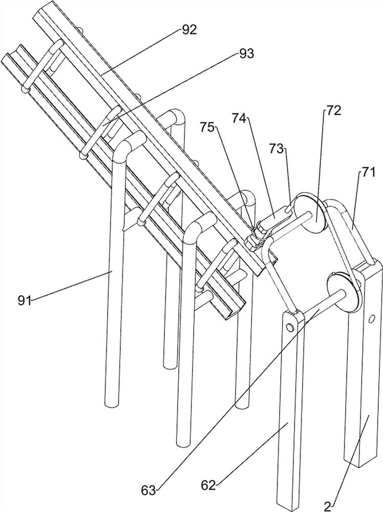
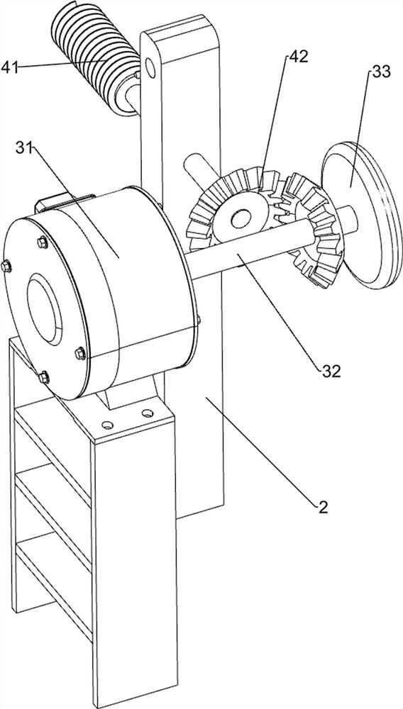
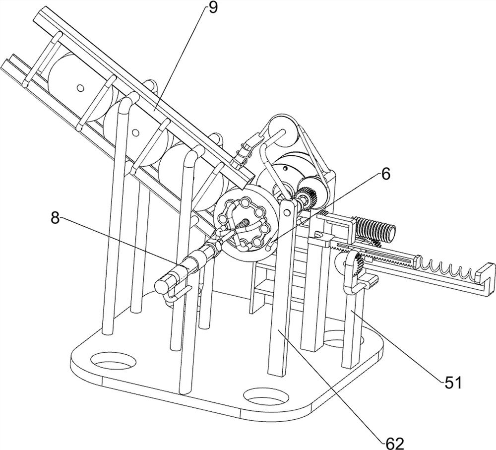
[0026] Such as Figure 1-6 As shown, a device for cutting and grinding the side of wooden round blocks according to the present invention includes a base plate 1, a mounting frame 2, a driving mechanism 3, a deceleration mechanism 4, a cutting mechanism 5 and a pressing mechanism 8, and the right front side of the top of the base plate 1 A mounting frame 2 is connected, a drive mechanism 3 is installed on the top right side of the bottom plate 1, a deceleration mechanism 4 is installed on the mounting frame 2, the deceleration mechanism 4 is connected to the drive mechanism 3 in transmission, a cutting mechanism 5 is installed on the front side of the top of the bott...


PUM


Abstract

The invention discloses a cutting and grinding device for the side edge of a wooden round block. The cutting and grinding device comprises a bottom plate, a mounting frame, a driving mechanism, a speed reducing mechanism, a cutting mechanism and a jacking mechanism, wherein one side of the bottom plate is connected with the mounting frame, the driving mechanism is arranged on the other side of thebottom plate, the speed reducing mechanism is arranged on the mounting frame, and the speed reducing mechanism is in transmission connection with the driving mechanism; the cutting mechanism is arranged on one side, close to the mounting frame, of the bottom plate, and the cutting mechanism is in transmission connection with the speed reducing mechanism; and the jacking mechanism is arranged on the other side of the bottom plate. According to the cutting and grinding device, the wooden round block can be limited through the jacking mechanism, so that the wooden round block is prevented from falling off; the speed reducing mechanism can be driven to work through the driving mechanism, the cutting mechanism can be driven to work through the speed reducing mechanism, and the side edge of thewooden round block can be cut and ground through the cutting mechanism so as to remove burrs.

Description

technical field [0001] The invention relates to a cutting and grinding device, in particular to a cutting and grinding device for the side of a wooden round block. Background technique [0002] There will be more burrs on the side of the newly cut wooden round block. In order to make the side of the wooden round block smooth, beautiful and convenient for the next step of processing, it is necessary to cut and polish the side of the wooden round block. In order to facilitate the cutting and grinding of the side of the wooden round block, the worker will make a round hole in the middle of the wooden round block, then put the wooden round block on the rotating device, and then make the rotating device carry the wooden round block Rotate, while the wooden round block is rotating, the worker manually holds the grinding block, so that the grinding block is close to the side of the wooden round block, so as to complete the cutting and grinding work on the side of the wooden round b...

Claims


Application Information

Patent Timeline
Patent Type & Authority Applications(China)
IPC IPC(8): B24B9/18B24B41/04B24B41/06B24B47/20B24B47/22B27C5/02B27C5/06
CPCB24B9/18B24B41/04B24B41/06B24B47/20B24B47/22B27C5/02B27C5/06
Inventor 陈四文
Owner 陈四文
Learn More