Scrap edge cutting device for iron building materials

A technology for edge cutting and building materials, applied in the direction of metal processing, etc., can solve the problems that the two sides of the cutter cannot be adjusted synchronously, cannot be used, and have poor practicability.

Pending Publication Date: 2021-03-12
常德祉博新型装饰材料有限责任公司
View PDF0 Cites 0 Cited by
  • Summary
  • Abstract
  • Description
  • Claims
  • Application Information

AI Technical Summary

Problems solved by technology

[0003] The prior art has the following disadvantages: the cutting knives on both sides of the cutting device cannot be adjusted synchronously, and manual adjustment is prone to errors, resulting in the inability to use the building materials after cutting, and poor practicability. Therefore, a cutting device for cutting waste edges of building materials that can accurately cut is proposed

Method used


Image

  • Scrap edge cutting device for iron building materials
  • Scrap edge cutting device for iron building materials
  • Scrap edge cutting device for iron building materials

Examples


Embodiment Construction

[0021] In order to facilitate the understanding of the present invention, the present invention will be described more fully below with reference to the associated drawings. Preferred embodiments of the invention are shown in the accompanying drawings. However, the present invention may be embodied in many different forms and is not limited to the embodiments described herein. On the contrary, the purpose of providing these embodiments is to make the disclosure of the present invention more thorough and comprehensive.

[0022] In describing the present invention, it is to be understood that the term "center" is used. "length", "width", "height", "top", "bottom", "front", "back", "left", "right", "vertical", "horizontal", "top", " The orientation or positional relationship indicated by "bottom", "inner", "outer" and "side" are based on the attached figure 1 The orientations or positional relationships shown are only for the convenience of describing the present invention and...


PUM


Abstract

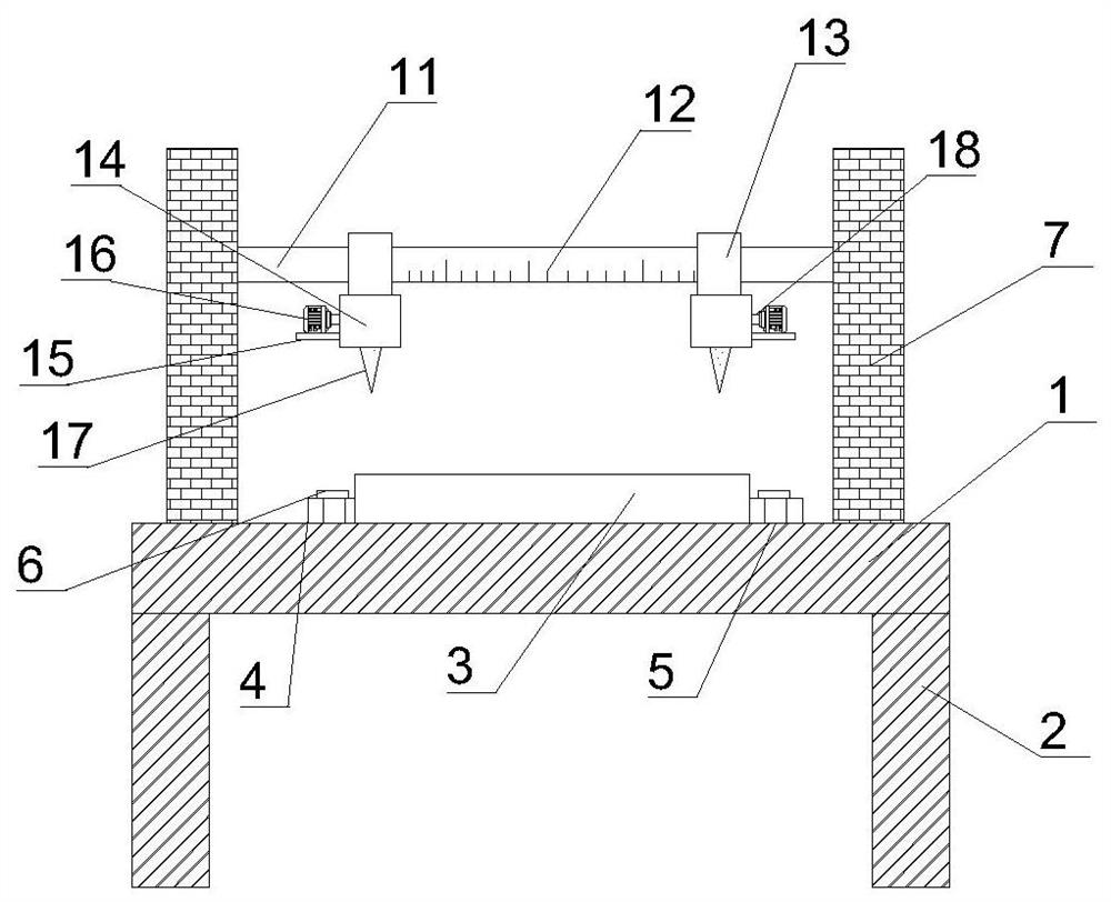
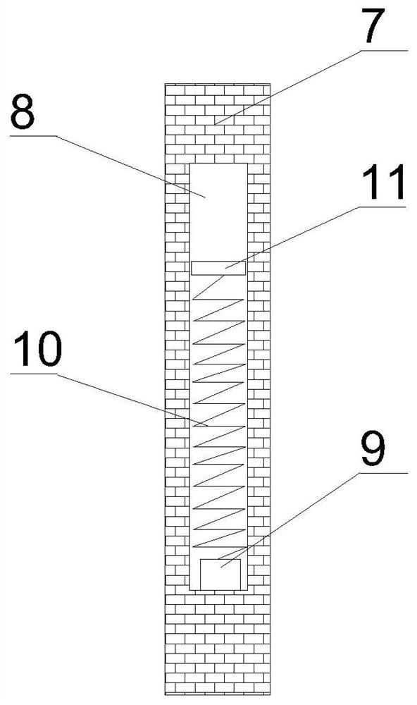
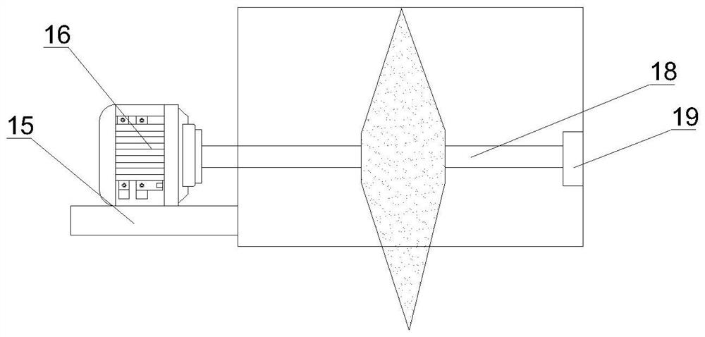
The invention discloses a scrap edge cutting device for iron building materials. The scrap edge cutting device for the iron building materials comprises a supporting table, wherein fixing plates are fixedly connected to the two sides of the top of the supporting table; empty cavities are formed in the opposite surfaces of the two fixing plates; fixing blocks are arranged at the bottoms of the empty cavities; springs are fixedly connected to the tops of the fixing blocks; scale plates are fixedly connected to the ends, away from the fixing blocks, of the springs; sliding seats are slidably connected to the scale plates and connected with a protective shell; a supporting rod is fixedly connected to the outer wall of the protective shell; a motor is arranged at the top of the supporting rod,and rotatably connected with a rotating shaft through an output end; the rotating shaft extends into the protective shell and is provided with a cutting knife; the cutting knife is driven to move up and down by vertically moving the scale plates; the motor drives the rotating shaft to rotate to drive the cutting knife to rotate, so that scrap edges of the building materials on a workbench can be conveniently cut; scales are formed on the scale plates, the sliding seats are slidably connected to the scale plates, and the cutting knife is driven to move in the horizontal direction by moving thesliding seats, so that the position of the cutting knife can be conveniently adjusted to realize accurate cutting.

Description

technical field [0001] The invention relates to the technical field of building material processing, in particular to an iron building material waste edge cutting device. Background technique [0002] The cutting device is a kind of equipment used by building materials and construction workers. After the polymer building material is processed into thermoplastic molding, it needs to be cut according to the design requirements, and the cutting device is needed to cut off the waste edges on both sides. [0003] The existing technology has the following disadvantages: the cutters on both sides of the cutting device cannot be adjusted synchronously, and manual adjustment is prone to errors, resulting in the inability to use the building materials after cutting, and poor practicability. Therefore, a cutting device for building material waste edges that can accurately cut is proposed. Contents of the invention [0004] Based on the deficiencies in the prior art mentioned in the a...

Claims


Application Information

Patent Timeline
IPC IPC(8): B26D1/28B26D5/06B26D5/08B26D7/02B26D7/20B26D7/22B26D7/28
CPCB26D1/28B26D5/06B26D5/086B26D7/02B26D7/20B26D7/22B26D7/28
Inventor 彭春艳
Owner 常德祉博新型装饰材料有限责任公司
Why Eureka
Try Eureka