Conveniently hoisted and quickly fixed steel truss lifting device

A steel truss, fast technology, applied in the direction of transportation and packaging, load hanging components, etc., can solve the problems of cumbersome, non-reusable, difficult lifting, etc., achieve the effect of reducing the cost of lifting, realizing fast fixing, and improving the problem of difficult lifting

Active Publication Date: 2021-03-12
CHINA HYDROPOWER ELEVENTH ENG BUREAU ZHENGZHOU CO LTD +1
View PDF6 Cites 0 Cited by
  • Summary
  • Abstract
  • Description
  • Claims
  • Application Information

AI Technical Summary

Problems solved by technology

[0004]The object of the present invention is to provide a steel truss lifting device that is convenient to lift, fix and fast in order to solve the above problems. At the same time, a jack is set on one side of the guide roller to push the steel truss to move, which improves the lifting difficulty caused by the friction between the steel truss and the ground in the existing hoisting method, and at the same time guides and protects the lifting process of the steel cable to avoid the vibration of the steel cable. The boom and the hoisting object are damaged by collision, and multiple sets of synchronously adjusted limit frames are installed at the bottom of the lifter to realize the rapid fixation of the hydraulic lifter. There are cumbersome welding and fixing problems and the problem that it cannot be reused, which reduces the cost of hoisting and has strong practicability. See the details below

Method used


Image

  • Conveniently hoisted and quickly fixed steel truss lifting device
  • Conveniently hoisted and quickly fixed steel truss lifting device
  • Conveniently hoisted and quickly fixed steel truss lifting device

Examples


Embodiment Construction

[0027] In order to make the purpose, technical solution and advantages of the present invention clearer, the technical solution of the present invention will be described in detail below. Apparently, the described embodiments are only some of the embodiments of the present invention, but not all of them. Based on the embodiments of the present invention, all other implementations obtained by persons of ordinary skill in the art without making creative efforts fall within the protection scope of the present invention.

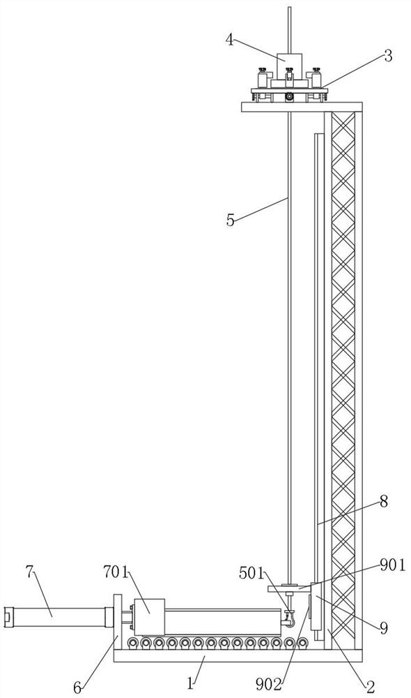
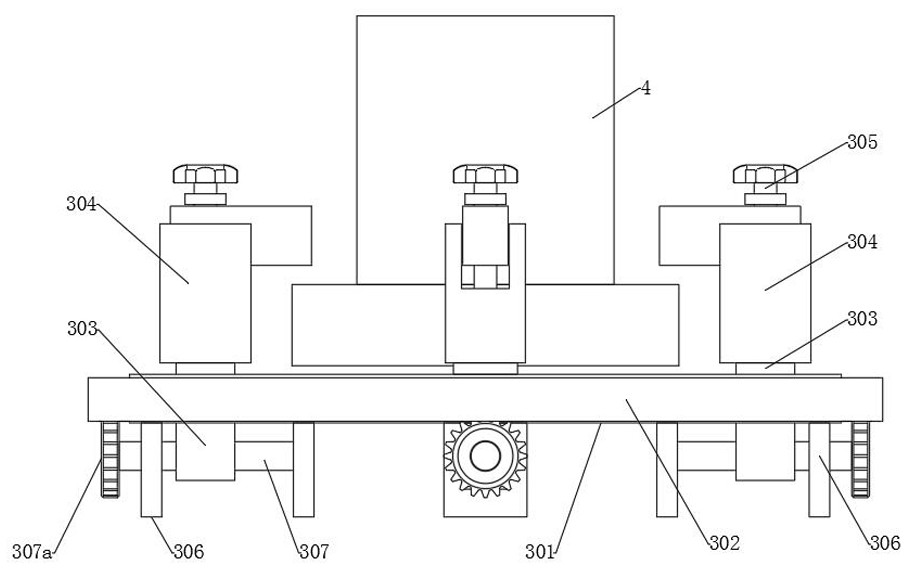
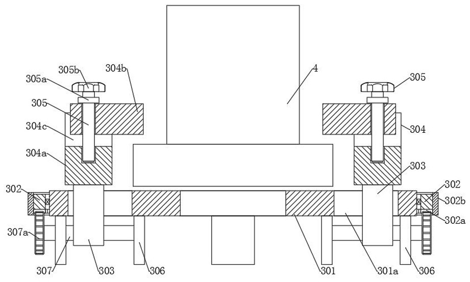
[0028] see Figure 1-Figure 5 As shown, the present invention provides a steel truss lifting device that is easy to lift and fix quickly, including an assembled tire frame 1 and a supporting frame 2, the assembled tire frame 1 extends laterally, and the supporting bracket 2 is vertically fixed to the assembled tire frame 1 On the top side, the top of the bracket 2 is provided with a fixing component 3;

[0029] The center of the top of the fixed component 3 is...


PUM


Abstract

The invention discloses a conveniently hoisted and quickly fixed steel truss lifting device which comprises an assembled bed-jig and a carrying bracket. The assembled jig-bed extends transversely, thecarrying bracket is vertically fixed to one side of the top of the assembled bed-jig, and a fixing assembly is arranged on the top of the carrying bracket; a hydraulic lifter is arranged at the center of the top of the fixing assembly, a steel strand is vertically arranged in the middle of the hydraulic lifter, a lifting hook is arranged at the bottom end of the steel strand, a steel truss is arranged on the top of the assembled jig-bed transversely, and the side, close to the carrying bracket, of the steel truss is detachably connected to the lifting hook. The conveniently hoisted and quickly fixed steel truss lifting device has the beneficial effects that by arranging a guide rail which supports the steel truss to move transversely on the surface of the assembled jig-bed and arranging ajack which pushes the steel truss to move on one side of the guide roller, a problem that it is hard to lift the steel truss as the steel truss and the ground generate a frictional force by an existing hoisting method is solved, and meanwhile, the device can be suitable for being used by various hydraulic lifters with different dimensions, and therefore, the hoisting cost is lowered and the conveniently hoisted and quickly fixed steel truss lifting device is high in practicality.

Description

technical field [0001] The invention relates to the field of building construction equipment, in particular to a steel truss lifting device which is convenient to lift and fast to fix. Background technique [0002] Steel trusses are trusses made of steel. Steel trusses are commonly used as the main load-bearing components for roof structures, crane beams, bridges and hydraulic gates of industrial and civil buildings. All kinds of towers, such as mast towers, TV towers and transmission line towers, are usually supported by space steel trusses composed of three-sided, four-sided or multi-sided planar trusses. During building construction, it is usually necessary to erect a lifting device to hoist the steel truss to the construction site. [0003] The applicant found that there are at least the following technical problems in the prior art: the steel truss hoisting device currently used needs to hoist the steel truss in the horizontal state to the vertical state for pulling u...

Claims


Application Information

Patent Timeline
Patent Type & Authority Applications(China)
IPC IPC(8): B66C1/14B66C13/06B66C13/08
CPCB66C1/14B66C13/06B66C13/08
Inventor 龚乐谢永强王奇涛郭以撒郭二浩
Owner CHINA HYDROPOWER ELEVENTH ENG BUREAU ZHENGZHOU CO LTD
Why Eureka
Try Eureka