
Electric supporting rod with overload protection function

An electric strut and overload protection technology, which is applied in the direction of automatic clutch, power control mechanism, wing leaf control mechanism, etc., can solve the problems of long fixed stroke of electric strut and difficulty of fixed stroke electric strut

Pending Publication Date: 2021-03-12
NINGBO TUOPU GROUP CO LTD
View PDF0 Cites 1 Cited by
  • Summary
  • Abstract
  • Description
  • Claims
  • Application Information

AI Technical Summary

Problems solved by technology

[0002] Electric struts have been widely used to open and close the tailgate of the car body, but the long fixed stroke of the electric strut for the tailgate of the sedan has always been a common problem
In some sedan trunks with relatively compact space, it is even more difficult to use electric struts with a long fixed stroke.

Method used


Image

  • Electric supporting rod with overload protection function
  • Electric supporting rod with overload protection function
  • Electric supporting rod with overload protection function

Examples


Embodiment 1

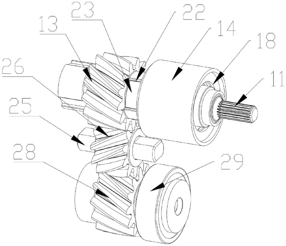
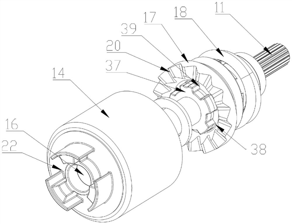
[0026] Embodiment 1: see Figure 1 to Figure 7: When the technical solution is in the no-overload state, the kinetic energy output by the motor after the motor in the second casing is energized and rotated will be output to the first rotating shaft through the reduction box provided by the motor, and because the first rotating shaft passes through the slider and the inner side wall of the separation disc The chute is slidingly connected, so the circumferential rotation of the first rotating shaft will drive the separation disc to perform circumferential rotation. At this time, the separation disc is inserted into the third housing through the first limit groove and the first limit protrusion near the end of the third housing, so the circumferential rotation of the separation disc will drive the third housing at the first position. Circumferential rotation is carried out in an accommodating cavity, so as to realize linkage output power to the casing. The side of the third hous...


PUM


Abstract

The invention discloses an electric supporting rod with an overload protection function. The electric supporting rod comprises a telescopic rod body of the electric supporting rod, wherein a first telescopic rod capable of driving the electric supporting rod to stretch out and draw back is connected into the telescopic rod body in a sliding mode, a telescopic structure is arranged in the first telescopic rod, and a first shell is fixedly connected to one end of the first telescopic rod; a first rotating mechanism for driving the telescopic structure to stretch out and draw back is rotationallyconnected into the first shell, a second shell is fixedly connected to the outer side wall of the first shell through a switching part, a first containing cavity is formed in the second shell, a second rotating mechanism is rotationally connected into the first containing cavity, and a motor for driving the second rotating mechanism to rotate is further arranged in the second shell; a third rotating mechanism is arranged in the switching part, the second rotating mechanism is rotationally connected with the first rotating mechanism through the third rotating mechanism, the second rotating mechanism comprises a first rotating shaft with one end rotationally connected with the motor, and an overload protection mechanism is rotationally connected to the outer side wall of the first rotatingshaft; and a first gear is rotationally connected to the outer side wall, away from the motor, of one end of the first rotating shaft, the first gear is connected with a filtering protection mechanismin an inserted mode, and the first gear is rotationally connected with the first rotating mechanism through the third rotating mechanism.

Description

technical field [0001] The invention relates to the technical field of vehicle electric tailgates, in particular to an electric strut with overload protection. Background technique [0002] Electric struts have been widely used to open and close the tailgate of the car body, but the long fixed stroke of the electric strut for the tailgate of the sedan has always been a common problem. In some compact sedan trunks, it is even more difficult to use an electric strut with a long fixed stroke. Contents of the invention [0003] Aiming at the deficiencies of the prior art, the present invention provides an electric strut with overload protection that can be installed in the trunk of a sedan with relatively compact space. [0004] An electric strut with overload protection of the present invention comprises a telescopic rod body of the electric strut, a first telescopic rod that can drive the electric strut to expand and contract is slidably connected to the telescopic rod body...

Claims


Application Information

Patent Timeline
IPC IPC(8): E05F15/622F16D43/21
CPCE05Y2201/216E05Y2900/532E05Y2900/548E05F15/622F16D43/215
Inventor 王正祥李全佑戴光林张志浩
Owner NINGBO TUOPU GROUP CO LTD
Learn More