
Iron powder inner ring type stainless steel magnetic seal bearing

A magnetic bearing, stainless steel technology, applied in the direction of bearings, bearing components, shafts and bearings, can solve the problems of difficult assembly, inability to assemble, unsafe production movement, etc., to achieve the effect of easy installation and maintenance, and increased pressure

Pending Publication Date: 2021-03-12
唐汉东 +1
View PDF0 Cites 0 Cited by
  • Summary
  • Abstract
  • Description
  • Claims
  • Application Information

AI Technical Summary

Problems solved by technology

[0002] The development of modern industrial technology requires a rotary sealing device that can completely isolate the external air (or liquid) from the internal environment without leakage under high temperature and high pressure, and can transmit power from the outside to the inside. The purpose is to Make the internal environment react in agitation, so as to obtain pure reaction substances, which is the commonly used magnetic seal bearing technology at present. However, magnetic fluid and magnetic force are affected by temperature and materials. It is very difficult or even impossible to assemble under the action; most of the current magnetic seal technology uses the magnetic fluid generated by the N.S pole magnetic field and the small gap between the magnetic field and the rotating shaft to add magnetic fluid to form a magnetic fluid sealing ring. The seal does not leak gas under rotation, but in a high-temperature and high-pressure environment, when the fluid in the magnetic fluid is heated and volatilizes and only iron powder is left, the seal will fail and leakage will occur during rotation, making the production movement extremely unsafe

Method used


Image

  • Iron powder inner ring type stainless steel magnetic seal bearing

Examples


Embodiment Construction

[0014] The present invention will be further described in detail below in conjunction with the accompanying drawings and specific embodiments to facilitate a clear understanding of the present invention, but they do not limit the present invention.

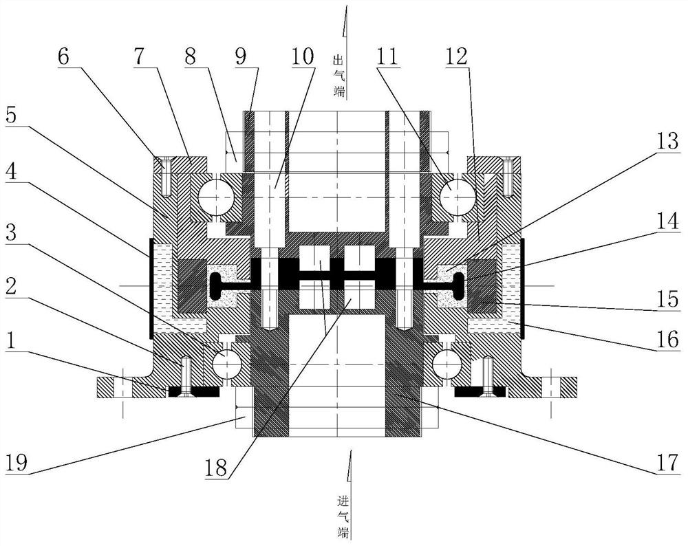
[0015] Such as figure 1 As shown, the present invention includes a magnetic bearing outer seat 5, the bottom of the magnetic bearing outer seat 5 is an air inlet end, and the top is an air outlet end, and also includes an upper power output shaft 9, a lower power shaft 17, and two symmetrical downward core bearings 3 , the upper radial bearing 11, the strong magnet 15, the air seal inner ring 14, two strong magnets 15 are symmetrically fixed in the magnetic bearing outer seat 5, and are pressed and fixed by the magnet pressing seat 12, the lower power shaft 17, the air seal inner ring The ring 14 and the upper power output shaft 9 are successively arranged in the outer seat 5 of the magnetic bearing from bottom to top, and are con...


PUM


Abstract

The invention discloses an iron powder inner ring type stainless steel magnetic seal bearing. The iron powder inner ring type stainless steel magnetic seal bearing comprises a magnetic bearing outer seat, an upper power output shaft, a lower power shaft, two symmetrical downward core bearings, an upper radial bearing, strong magnets and air seal inner rings, wherein the bottom of the magnetic bearing outer seat is an air inlet end, and the top of the magnetic bearing outer seat is an air outlet end; the two strong magnets are symmetrically fixed in the magnetic bearing outer seat and are pressed and fixed through a magnet pressing seat; the lower power shaft, the air seal inner rings and the upper power output shaft are sequentially arranged in the magnetic bearing outer seat from bottom to top and are connected through an upper output power shaft screw; iron powder grooves are formed between the inner sides of the strong magnets and the magnet pressing seat; iron powder is arranged inthe iron powder grooves; the outer ends of the two air seal inner rings are located in the iron powder grooves respectively; and the inner ends of the two air seal inner rings are connected through aconnecting key. According to the iron powder inner ring type stainless steel magnetic seal bearing, metal magnetic interference is not generated in the assembling process of the magnetic bearing.

Description

technical field [0001] The invention belongs to the technical field of novel magnetic seal bearings, in particular to an iron powder inner ring type stainless steel magnetic seal bearing. Background technique [0002] The development of modern industrial technology requires a rotary sealing device that can completely isolate the external air (or liquid) from the internal environment without leakage under high temperature and high pressure, and can transmit power from the outside to the inside. The purpose is to Make the internal environment react in agitation, so as to obtain pure reaction substances, which is the commonly used magnetic seal bearing technology at present. However, magnetic fluid and magnetic force are affected by temperature and materials. It is very difficult or even impossible to assemble under the action; most of the current magnetic seal technology uses the magnetic fluid generated by the N.S pole magnetic field and the small gap between the magnetic fie...

Claims


Application Information

Patent Timeline
IPC IPC(8): F16C32/04F16C33/72F16C33/76F16C37/00F16J15/53F16J15/43
CPCF16C32/0402F16C33/72F16C33/765F16C37/005F16J15/43
Inventor 唐汉东
Owner 唐汉东
Learn More