Compact lip labyrinth shaft sealing unit, corresponding shaft seal and corresponding carrier roller

A shaft sealing, compact technology, applied in the direction of bearing components, shafts and bearings, rollers, etc., can solve the problems of small rotation resistance, large rotation resistance, and high allowable speed of labyrinth seals, and achieve good sealing effect, compact structure, The effect of high allowable speed

Pending Publication Date: 2021-03-12
兖矿能源集团股份有限公司 +1
View PDF1 Cites 1 Cited by
  • Summary
  • Abstract
  • Description
  • Claims
  • Application Information

AI Technical Summary

Problems solved by technology

The labyrinth seal has small rotation resistance and high allowable speed; the advantage is that the contact seal method has a good sealing effect, but the disadvantage is that the rotation resistance is large and the allowable speed is low
[0003] The Chinese utility model published on March 13, 2018, with the publication number CN 207090383 U, discloses a composite sealing roller for a logistics conveyor belt. This patent only uses a labyrinth seal and a contact seal at the same time. It is just a simple superposition of the two sealing methods. The effect is limited
Can not meet the use requirements of high-speed belt conveyor

Method used


Image

  • Compact lip labyrinth shaft sealing unit, corresponding shaft seal and corresponding carrier roller
  • Compact lip labyrinth shaft sealing unit, corresponding shaft seal and corresponding carrier roller
  • Compact lip labyrinth shaft sealing unit, corresponding shaft seal and corresponding carrier roller

Examples


Embodiment approach 1

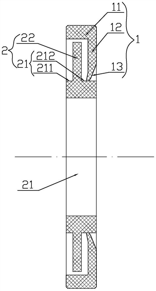
[0021] Implementation mode one: if figure 1 As shown, the compact lip labyrinth shaft seal unit includes an L-shaped outer seal ring 1, which is characterized in that it also includes a T-shaped inner seal ring 2, and the T-shaped inner seal ring 2 includes a shaft sleeve ring 21 and a spacer ring 22. The inner edge of the spacer ring 22 is fixedly connected to the outer circumference of the sleeve ring 21, and the two are integrally formed, and the spacer ring 22 divides the sleeve ring into an inner ring part 211 and an outer ring part 212. The T-shaped The shaft sleeve ring 21 of the inner sealing ring 2 is tightly fitted on the matching shaft ( figure 1 not shown, see Figure 2-4 ), the inner and outer end faces of the sleeve ring 21 of the T-shaped inner seal ring 2 are directly or indirectly clamped between the inner ring of the matching bearing and the spring retaining ring for the matching shaft, and are fixed on the matching shaft ( figure 1 not shown, see Figure ...

Embodiment approach 2

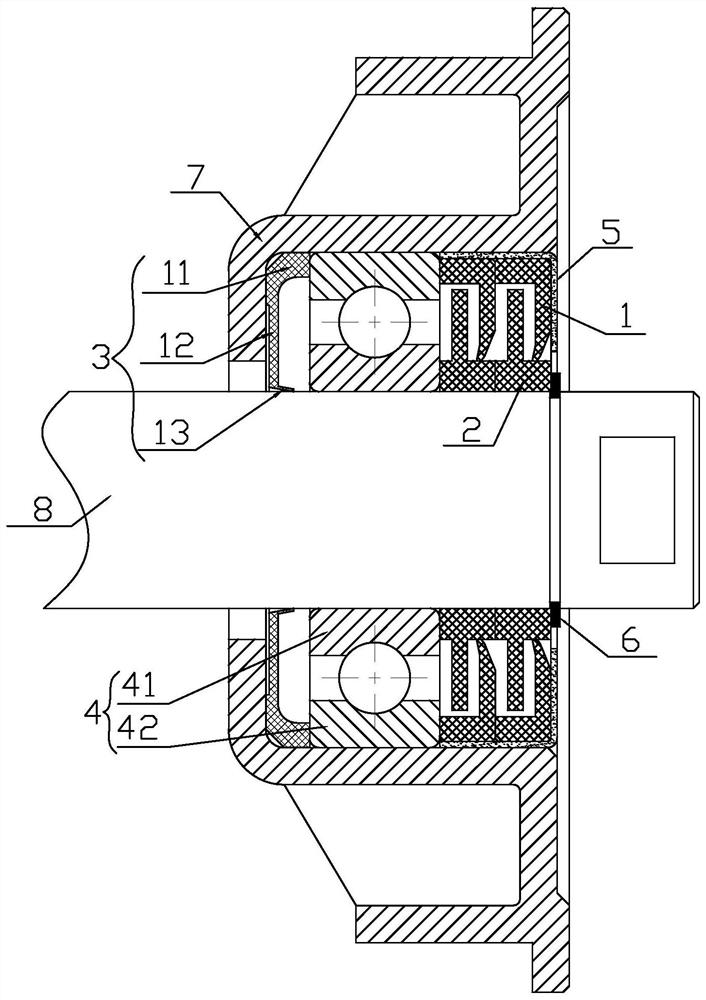
[0024] Implementation mode two: if figure 2 As shown, the shaft seal of the present invention includes a sealing ring 3, a bearing 4, an L-shaped retaining ring 5 and a spring retaining ring 6 for the shaft, and a matching bearing seat 7, a sealing ring 3, a bearing 4, an L-shaped retaining ring 5 and a shaft The retaining ring 6 is set on the matching shaft 8, the sealing ring 3, the bearing 4, the L-shaped retaining ring 5 and the spring retaining ring 6 for the shaft are all located in the matching bearing seat 7, and are arranged in sequence from the inside to the outside , is characterized in that: it also includes two sets of the aforementioned compact lip labyrinth shaft seal unit, the above-mentioned compact lip labyrinth shaft seal unit is sleeved side by side on the matching shaft 8 between the bearing 4 and the L-shaped retaining ring 5 Above, the lip ring 12 of each compact lip labyrinth shaft seal unit is located on the outer side of the spacer ring 22 of its mat...

Embodiment approach 3

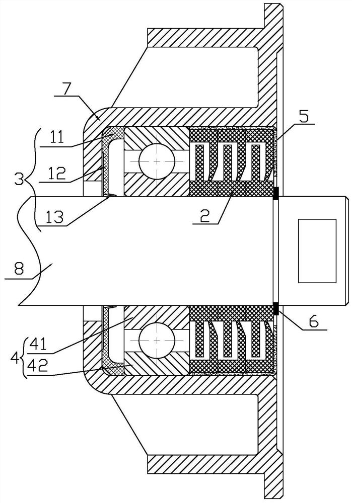
[0026] Implementation mode three: if image 3 As shown, the shaft seal of the present invention includes a sealing ring 3, a bearing 4, an L-shaped retaining ring 5 and a spring retaining ring 6 for the shaft, and a matching bearing seat 7, a sealing ring 3, a bearing 4, an L-shaped retaining ring 5 and a shaft The retaining ring 6 is set on the matching shaft 8, the sealing ring 3, the bearing 4, the L-shaped retaining ring 5 and the spring retaining ring 6 for the shaft are all located in the matching bearing seat 7, and are arranged in sequence from the inside to the outside , is characterized in that: it also includes three sets of the aforementioned compact lip labyrinth shaft sealing units, and the rest of the structure is as described in Embodiment 2, omitted.


PUM


Abstract

The invention relates to a compact lip labyrinth shaft sealing unit, a corresponding shaft seal and a corresponding carrier roller. In order to overcome the defects in the prior art, the compact lip labyrinth shaft sealing unit comprises an L-shaped outer sealing ring and a T-shaped inner sealing ring, wherein the T-shaped inner sealing ring comprises a shaft sleeve ring and a spacer ring, the inner edge of the spacer ring is fixedly connected to the outer circumference of the shaft sleeve ring, the spacer ring divides the shaft sleeve ring into an inner ring part and an outer ring part, and the shaft sleeve ring of the T-shaped inner sealing ring tightly sleeves a matched shaft; the L-shaped outer sealing ring comprises a clamping ring and a lip ring, the outer edge of the lip ring is fixedly connected to the outer edge of the clamping ring, the inner edge of the lip ring is provided with a lip edge bent inwards, the outer ring portion of the T-shaped inner sealing ring is sleeved with the lip edge in a pressed mode, and the L-shaped outer sealing ring is tightly clamped on the inner circumferential wall of a matched bearing base and can rotate along with the matched bearing base.The invention also relates to a corresponding shaft seal and a carrier roller. The compact lip labyrinth shaft sealing unit is compact in structure, good in sealing effect, suitable for various rotary shafts and particularly suitable for being used in cooperation with a belt conveyor.

Description

technical field [0001] The invention relates to a compact lip labyrinth shaft seal unit, a corresponding shaft seal and a corresponding idler roller. Background technique [0002] The existing roller bearings generally adopt sealing structures such as labyrinth seals or contact seals. The labyrinth seal has small rotation resistance and high allowable speed; the advantage is that the contact seal method has a good sealing effect, but the disadvantage is that the rotation resistance is large and the allowable speed is low. [0003] The Chinese utility model published on March 13, 2018, with the publication number CN 207090383 U, discloses a composite sealing roller for a logistics conveyor belt. This patent only uses a labyrinth seal and a contact seal at the same time. It is just a simple superposition of the two sealing methods. The effect is limited. The prior art urgently needs a new type of shaft seal with small axial dimension and good sealing effect. [0004] At pre...

Claims


Application Information

Patent Timeline
Patent Type & Authority Applications(China)
IPC IPC(8): F16C33/78F16C33/80B65G39/09B65G39/02
CPCB65G39/02B65G39/09F16C33/7806F16C33/7823F16C33/783F16C33/7896F16C33/80F16C2326/58
Inventor 裴计田姜海杨澎王春奇朱述川郑立本曹剑管庆霞刘志坚付友李双忠孙严伟袁向科李文达
Owner 兖矿能源集团股份有限公司
Why Eureka
Try Eureka