
Electric water valve locked-rotor control method and controller

A control method and controller technology, applied in valve details, valve devices, engine components, etc., can solve problems such as shortening the life of electric water valves, reduce the possibility of gear stuck, reduce wear, and reduce impact effect

Pending Publication Date: 2021-03-12
ZHEJIANG YINLUN MACHINERY
View PDF7 Cites 0 Cited by
  • Summary
  • Abstract
  • Description
  • Claims
  • Application Information

AI Technical Summary

Problems solved by technology

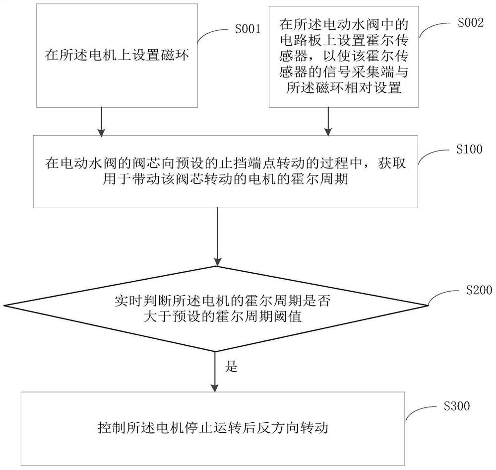
[0005] The purpose of this application is to provide an electric water valve stall control method and controller for the problem that the life of the electric water valve is reduced due to the existing electric water valve stall control method

Method used


Image

  • Electric water valve locked-rotor control method and controller
  • Electric water valve locked-rotor control method and controller
  • Electric water valve locked-rotor control method and controller

Examples


Embodiment Construction

[0052] The technical solutions of the present application will be clearly and completely described below in conjunction with the accompanying drawings. Apparently, the described embodiments are some of the embodiments of the present application, not all of them. Based on the embodiments in this application, all other embodiments obtained by persons of ordinary skill in the art without making creative efforts belong to the scope of protection of this application.

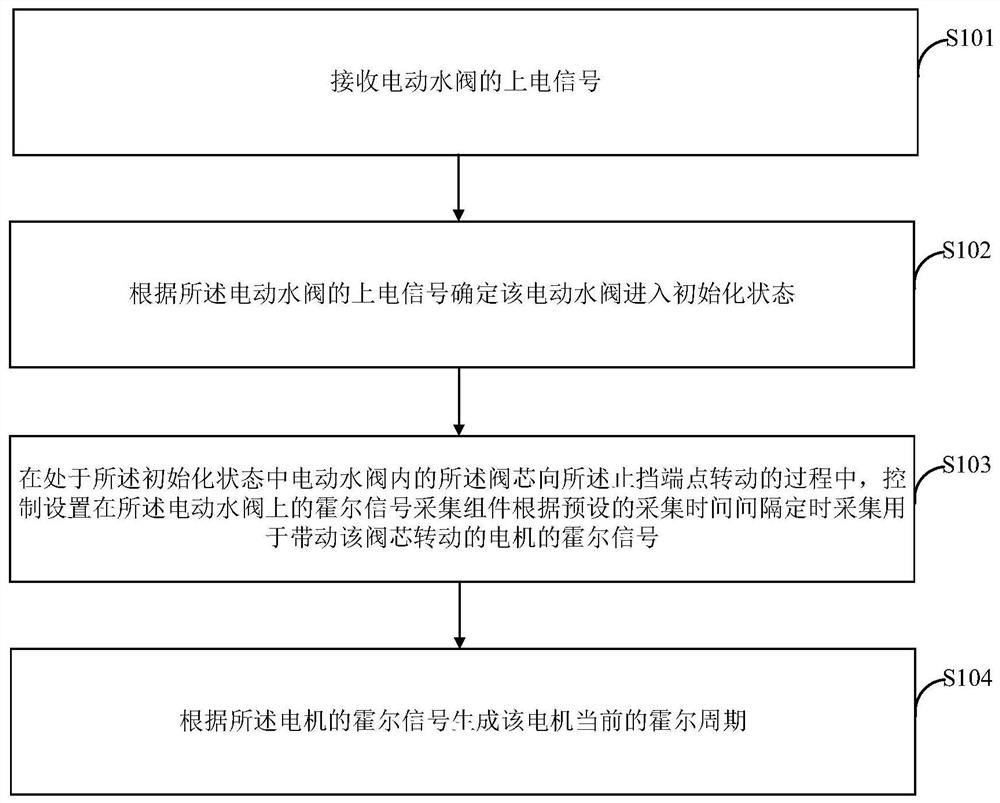
[0053] The current blocking control method of the electric water valve is that when the electric water valve is powered on, the electric water valve will be initialized, that is, the valve core will rotate from the position before power on to the fully open position. After the gear position, the valve core is stuck, causing the gear train and the motor to not rotate, and the Hall number does not change at the same time. After the system detects that the Hall of the water valve remains unchanged, the water valve will g...


PUM


Abstract

The invention relates to the technical field of valves, in particular to an electric water valve locked-rotor control method and a controller. The control method comprises the steps that a Hall periodof a motor for driving a valve core to rotate is obtained in a process that the valve core of an electric water valve rotates to a preset stop endpoint; whether the Hall period of the motor is largerthan a preset Hall period threshold value or not is judged in real time, and if yes, the motor is controlled to rotate in the reverse direction after stopping running. The invention aims to provide the electric water valve locked-rotor control method and the controller in order to solve the problem that the service life of the electric water valve is shortened due to an existing electric water valve locked-rotor control scheme.

Description

technical field [0001] The present application relates to the technical field of valves, in particular, to a method and controller for controlling stalling of electric water valves. Background technique [0002] The electric water valve is mainly used in the cooling system of new energy vehicles, and its function is to switch the flow direction of the medium in the cooling system or perform proportional adjustment. The working principle of the electric water valve is: the motor drives the gear train. After the gear train decelerates, the power is finally transmitted to the valve core, which drives the valve core to rotate. There is a flow hole on the valve core. By changing the valve core flow hole and the valve body The relationship between the upper runner openings is used to change the flow direction or proportional adjustment of the medium. [0003] In the electric water valve structure, a mechanical stop will be set on the valve body to control the rotation angle of th...

Claims


Application Information

Patent Timeline
IPC IPC(8): F16K31/04F16K37/00
CPCF16K31/042F16K37/0083
Inventor 马俊
Owner ZHEJIANG YINLUN MACHINERY
Learn More