Ventilation system and control method thereof
A technology of fresh air system and fresh air blower, which is applied in the direction of ventilation system, heating and ventilation control system, heating and ventilation safety system, etc. It can solve the problem of not being able to solve the problem of pipeline condensation and achieve the effect of avoiding condensation
- Summary
- Abstract
- Description
- Claims
- Application Information
AI Technical Summary
Problems solved by technology
Method used
Image

Examples
Embodiment 1
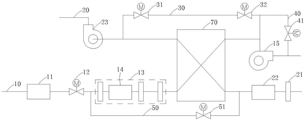
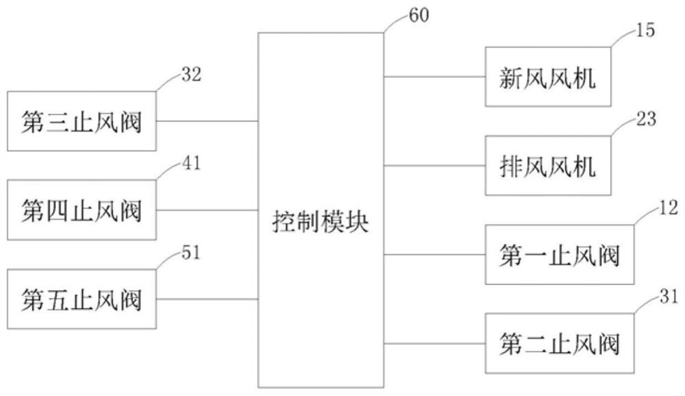
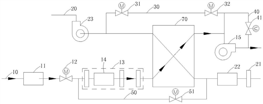
[0056] A fresh air system, see figure 1 and figure 2 , including a fresh air duct 10 , an exhaust duct 20 , a first duct 30 , and a control module 60 . Wherein, the fresh air duct 10 is used to send outdoor air into the room. Specifically, along the direction in which the air flow flows from outdoor to indoor in the fresh air duct 10, a first air stop valve 12, a fresh air blower, and a first air stop valve 12 are sequentially arranged on the fresh air duct 10. 15. The exhaust duct 20 is used to discharge indoor air to the outside, and an exhaust fan 23 is arranged on the exhaust duct 20 . One end of the first pipeline 30 is arranged between the first air stop valve 12 and the fresh air blower 15, the other end of the first pipeline 30 communicates with the air inlet side of the exhaust fan 23, and the first pipeline 30 is provided with a second wind stop Valve 31. The control module 60 is electrically connected to the first air stop valve 12 , the fresh air fan 15 , the ...
Embodiment 2
[0088] A fresh air system, see Figure 8 , Figure 9 , Figure 10 ,in, Figure 9 and Figure 10 The arrows in are pointing to the airflow direction. The difference between the fresh air system described in this embodiment and the fresh air system described in Embodiment 1 is that it further includes a body 80 , and the fresh air system described in Embodiment 1 is integrated into a body 80 .
[0089] Specifically, the heat exchanger 70 is disposed in the middle of the body 80 . The air inlet and the air outlet of the fresh air duct 10 are respectively arranged on the left side and the right side of the body 80; according to the direction in which the outdoor air flows into the room, the above-mentioned raindrop detection module 11 and the first wind stop are installed on the fresh air duct 10 in sequence. Valve 12, primary filter, first sensor module 14, high-efficiency filter, activated carbon filter, heat exchanger 70, fresh air blower 15. The air inlet and the air out...
Embodiment 3
[0094] A fresh air system, which differs from the fresh air system described in Embodiment 1 or Embodiment 2 in that it also includes a wall-type air outlet device (not shown in the figure), and the wall-type air outlet device can be installed on a window or on a On the wall within 0.5 meters from the window frame. Wherein, the wall-type air outlet device is a wall-type air inlet device sold on the market, and its specific structure will not be discussed here. The window can be a window that can be ventilated, such as a sliding window, a window, a shutter, etc., and the window can also be a window that cannot be ventilated, such as a curtain wall. Through this design, on the one hand, the effect of air supply or exhaust can be improved; on the other hand, the installation of the air outlet needs to open holes on the wall. Considering that there are generally no load-bearing walls near the windows, openings near the windows Holes and installation of air vents will not cause to...
PUM
 Abstract
Description
Claims
Application Information
 - R&D
- Intellectual Property
- Life Sciences
- Materials
- Tech Scout
- Unparalleled Data Quality
- Higher Quality Content
- 60% Fewer Hallucinations
Browse by: Latest US Patents, China's latest patents, Technical Efficacy Thesaurus, Application Domain, Technology Topic, Popular Technical Reports.
© 2025 PatSnap. All rights reserved.Legal|Privacy policy|Modern Slavery Act Transparency Statement|Sitemap|About US| Contact US: help@patsnap.com