Wireless inclinometer for long-distance test site

An on-site, long-distance technology, applied in the field of wireless inclinometers, can solve the problems of inconvenient long-distance inclinometer tube point-by-point measurement, inability to measure inclinometer tubes, etc.

Inactive Publication Date: 2021-03-12
陕西航宇星测科技有限公司
View PDF2 Cites 0 Cited by
  • Summary
  • Abstract
  • Description
  • Claims
  • Application Information

AI Technical Summary

Problems solved by technology

[0007] The purpose of the present invention is to solve the problem that the wireless inclinometer in the prior art is not convenient to measure long-distance inclinometer tubes at the same interval point by point, and can not measure the inclinometer tubes with different diameters. A wireless inclinometer for long-distance test site

Method used


Image

  • Wireless inclinometer for long-distance test site
  • Wireless inclinometer for long-distance test site
  • Wireless inclinometer for long-distance test site

Examples


Embodiment 1

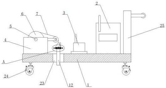
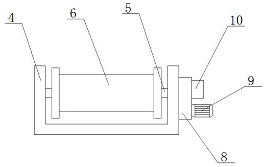
[0025] Example 1, such as Figure 1-3 , this wireless inclinometer for long-distance test site includes a base 1, a display control terminal 2 and a data transceiver device 3 are installed on the upper end of the base 1, and a U-shaped mounting frame 4 is fixedly connected to the upper end of the base 1, and the mounting frame 4 is opposite to each other. The side wall is rotatably connected with a rotary rod 5 through two first bearings, a storage reel 6 is fixedly sleeved on the rotary rod 5, a traction wire rope 7 is wound on the storage reel 6, and a speed reducer is installed on the outer wall of the mounting frame 4. 8, one end of the rotating rod 5 is connected to the output end of the reducer 8, a motor 9 is installed on the reducer 8, the input end of the reducer 8 is connected to one end of the rotating shaft of the motor 9, and a motor governor is installed on the reducer 8 10. One end of the traction wire rope 7 is fixedly connected with two nylon ropes 11, and the...

Embodiment 2

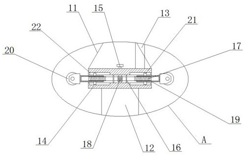
[0026] Embodiment 2 is on the basis of embodiment 1 such as image 3 As shown, the upper end of its casing 12 is fixedly connected with an adjustment cylinder 14, and the adjustment cylinder 14 is connected with a worm 15 through two second bearings for common rotation, and the upper end of the worm 15 is fixedly connected with a turntable, and the inside of the adjustment cylinder 14 is symmetrically fixed with respect to the worm 15. A partition 16 is connected, and the two partitions 16 are jointly rotated and connected with a threaded rod 17 through two third bearings. The walls of the threaded rod 17 are provided with threads in opposite directions. 17 rod walls are fixedly sleeved with worm gear 18, and worm gear 18 and worm screw 15 are meshed, threaded sleeve 19 is threaded symmetrically about worm gear 18 on the threaded rod 17 rod wall, and one end of threaded sleeve 19 is equipped with guide wheel 20, threaded The limit block 21 is symmetrically fixedly connected to...

Embodiment 3

[0027] Embodiment 3 is such as on the basis of embodiment 1 figure 1 and image 3 As shown, a movable hole 23 is provided on its base 1, and the aperture of the movable hole 23 is larger than the distance between the two guide wheels 20, so that the casing 12 can be used directly through the movable hole 23.


PUM


Abstract

The invention relates to the technical field of wireless inclinometers, and discloses a wireless inclinometer for a long-distance test site. The wireless inclinometer comprises a base, a display control terminal and a data transceiving device are mounted at the upper end of the base, and a U-shaped mounting frame is fixedly connected to the upper end of the base. A rotating rod is rotatably connected to the opposite side walls of the mounting frame through two first bearings, the rotating rod is fixedly sleeved with a storage winding drum, a traction steel wire rope is wound around the storagewinding drum, a speed reducer is mounted on the outer side wall of the mounting frame, one end of the rotating rod is connected with the output end of the speed reducer, a motor is mounted on the speed reducer, and the input end of the speed reducer is connected with one end of a rotating shaft of the motor. The traction steel wire rope can be uniformly and automatically paid off, point-by-pointmeasurement with the same interval can be conveniently carried out on long-distance inclinometry pipes, the interval between two guide wheels can be adjusted, and inclinometry pipes with different diameters can be measured.

Description

technical field [0001] The invention relates to the technical field of wireless inclinometers, in particular to a wireless inclinometer for long-distance test sites. Background technique [0002] During the construction of buildings, highways, dams and other projects and in the following years, it is necessary to monitor the oblique deformation and settlement deformation of the main body of the construction. Generally, the inclinometer tube is installed on the section to be detected, and the mobile inclination measuring head is used to measure point by point at equal intervals in the inclinometer tube. [0003] The existing patent (announcement) No. CN202209946U discloses a wireless inclinometer, which uses the ground controller to receive inclination data through the ground control antenna, wireless transceiver module and microprocessor, and transmits the inclination angle through the remote transceiver module and the remote module transceiver antenna. Data, reducing the w...

Claims


Application Information

Patent Timeline
IPC IPC(8): G01C9/02G08C17/02
CPCG01C9/02G08C17/02
Inventor 张拴祥周秋绒
Owner 陕西航宇星测科技有限公司
Why Eureka
Try Eureka