
Filter pressing testing device

A test device, hydraulic technology, applied in the direction of measuring devices, mechanical devices, instruments, etc., can solve the problems of affecting test results, low maximum pressure, and difficulty in taking out materials

Active Publication Date: 2021-03-12
JIANGSU FEYMER TECH
View PDF10 Cites 0 Cited by
  • Summary
  • Abstract
  • Description
  • Claims
  • Application Information

AI Technical Summary

Problems solved by technology

Existing test devices are generally driven by air pressure, the maximum pressure is low, and cannot simulate the pressure requirements of the on-site plate and frame machine
During the compression process, the water produced by the material cannot be well drained, which affects the test results
After the compression is completed, it is difficult to take out the material, which increases the workload of the test

Method used


Image

  • Filter pressing testing device
  • Filter pressing testing device

Examples


Embodiment Construction

[0017] The technical solution of the present invention will be further described below in conjunction with the accompanying drawings.

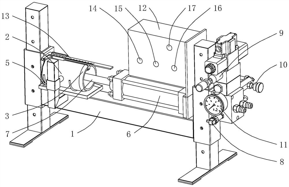
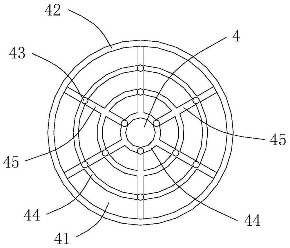
[0018] see Figure 1-2 As shown, the above-mentioned filter press test device includes a frame 1, an outer sleeve 2 fixed on the frame 1, a fixed ring against the first orifice plate at one end of the outer sleeve 2, and can be rotated along its own axis. The inner sleeve 3 in the outer sleeve 2 that can be plugged and inserted in the direction of the line, two second orifice plates 4 that can move along the axial direction of the inner sleeve 3 and ring against the inner sleeve 3, set The water tray 5 on the frame 1 and below the outer sleeve 2 .

[0019] see figure 1 As shown, in this embodiment, the outer sleeve 2 is fixedly connected with the frame 1 through its side and bottom. The first orifice plate is connected to the left end of the outer sleeve 2, and the two are integrally formed. The outer sleeve 2, the first orifice plate, the...


PUM


Abstract

The invention discloses a filter pressing testing device. The device comprises a rack, an outer sleeve fixedly arranged on the rack, a fixed first pore plate which annularly abuts against one end of the outer sleeve, an inner sleeve which is arranged in the outer sleeve in a pluggable mode in the axis direction of the inner sleeve, two second pore plates which can move in the axis direction of theinner sleeve and annularly abut against the interior of the inner sleeve, a water pan which is arranged on the rack and located below the outer sleeve, a hydraulic driving mechanism which is arrangedon the rack and used for driving one of the second pore plates to move in the inner sleeve, and a measuring mechanism which is arranged on the outer sleeve and used for measuring the displacement ofthe second pore plate. According to the filter pressing testing device, water is drained thoroughly during filter pressing, materials can be taken out conveniently after filter pressing is completed,and the maximum testing pressure is high.

Description

technical field [0001] The invention relates to a pressure filter test device. Background technique [0002] At present, the pressure filtration experiment of materials is generally realized through testing devices. Existing test devices are generally driven by air pressure, the maximum pressure is low, and cannot simulate the pressure requirements of the on-site panel and frame machine. During the compression process, the water produced by the material cannot be well drained, which affects the test results. After the compression is completed, it is difficult to take out the material, which increases the workload of the test. Contents of the invention [0003] The purpose of the present invention is to provide a filter press testing device, which can drain water thoroughly during the press filter, and can conveniently take out the material after the press filter is completed, and the maximum test pressure is relatively high. [0004] In order to achieve the above object...

Claims


Application Information

Patent Timeline
Patent Type & Authority Applications(China)
IPC IPC(8): G01N19/00
CPCG01N19/00Y02E30/30
Inventor 杨俊欢闫武军翟忠宝朱立波耿丽霞
Owner JIANGSU FEYMER TECH
Learn More