Equipment for quickly stripping optical fiber

An optical fiber and equipment technology, applied in the field of equipment for rapid optical fiber stripping, can solve the problems of optical fiber damage, influence, and low efficiency, and achieve the effects of high efficiency, improved precision, and high degree of accuracy

Inactive Publication Date: 2021-03-12
福州妆缘红电子科技有限公司
View PDF0 Cites 2 Cited by
  • Summary
  • Abstract
  • Description
  • Claims
  • Application Information

AI Technical Summary

Problems solved by technology

[0002] Optical fiber connector is a device for detachable (movable) connection between optical fiber and optical fiber. It precisely butts the two end faces of optical fiber so that the optical energy output by the transmitting optical fiber can be coupled to the receiving optical fiber to the maximum extent. And to minimize the impact on the system due to its intervention in the optical link, this is the basic requirement of the optical fiber connector. To a certain extent, the optical fiber connector affects the reliability and performance of the optical transmission system. In the optical fiber The optical fiber needs to be processed before connection, including stripping the fiber skin, cutting off the unnecessary optical fiber, and wiping the surface of the optical fiber. Manual operation requires many steps, and the efficiency is not high, and it is easy to cause damage to the optical fiber. Therefore, it is necessary to develop a high-efficiency stripping fiber optic equipment

Method used


Image

  • Equipment for quickly stripping optical fiber
  • Equipment for quickly stripping optical fiber
  • Equipment for quickly stripping optical fiber

Examples


Embodiment Construction

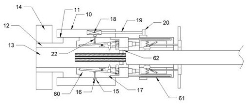
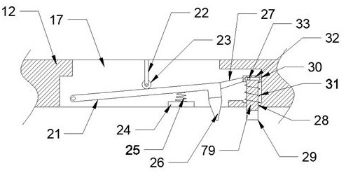
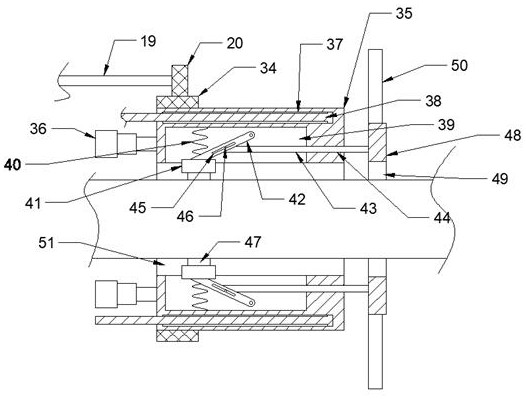
[0017] Combine below Figure 1-5 The present invention is described in detail, wherein, for the convenience of description, the orientations mentioned below are defined as follows: figure 1 The up, down, left, right, front and back directions of the projection relationship itself are the same.

[0018] A device for quickly stripping optical fibers described in conjunction with accompanying drawings 1-5 includes an adjustment sleeve 10, and the adjustment sleeve 10 is provided with a left and right transparent transmission hole 11, and the inner wall of the transmission hole 11 is provided with threads. The transmission hole 11 is internally threaded with an adjustment body 12, and the adjustment body 12 is provided with a left and right through groove 13, and the left side of the adjustment body 12 is fixed on the left side of the transmission hole 11, and an adjustment handle 14 is fixed. The upper and lower walls of the passing groove 13 are symmetrically provided with a sh...


PUM


Abstract

The invention discloses equipment for quickly stripping an optical fiber. The equipment comprises an adjusting sleeve which is internally provided with a transmission hole which is through from left to right, the inner wall of the transmission hole is provided with a thread, the interior of the transmission hole is in threaded connection with an adjusting body, and the adjusting body is internallyprovided with a through groove which is through from left to right, and an adjusting handle is fixedly arranged on the left side of the adjusting body and located on the left side of the transmissionhole. By using the equipment, a sheath of the optical fiber is stripped according to the set depth, personnel participation is not needed in the working process, the automation degree is high, the device is provided with the shearing mechanism 62, and a shearing mechanism 62 can be used for shearing two optical fibers of the same optical fiber according to the requirement, the functions of distinguishing optical fibers of different colors and automatically cutting off unnecessary optical fibers are achieved, the shearing angle and position can be automatically judged, the shearing precision is improved, mistaken cutting off is avoided, the accuracy degree is high, and the efficiency is high.

Description

technical field [0001] The invention relates to a device for quickly stripping optical fibers, and mainly relates to the field of photoelectric connectors. Background technique [0002] Optical fiber connector is a device for detachable (movable) connection between optical fiber and optical fiber. It precisely butts the two end faces of optical fiber so that the optical energy output by the transmitting optical fiber can be coupled to the receiving optical fiber to the maximum extent. And to minimize the impact on the system due to its intervention in the optical link, this is the basic requirement of the optical fiber connector. To a certain extent, the optical fiber connector affects the reliability and performance of the optical transmission system. In the optical fiber The optical fiber needs to be processed before connection, including stripping the fiber skin, cutting off the unnecessary optical fiber, and wiping the surface of the optical fiber. Manual operation requi...

Claims


Application Information

Patent Timeline
Patent Type & Authority Applications(China)
IPC IPC(8): G02B6/245G02B6/25
CPCG02B6/245G02B6/25
Inventor 李扎
Owner 福州妆缘红电子科技有限公司
Why Eureka
Try Eureka