Air defense missile trajectory modeling method based on aerodynamic fixed connection coordinate system

A modeling method and anti-aircraft missile technology, applied in the fields of instruments, electrical digital data processing, computer-aided design, etc., can solve the problems of complex coordinate transformation of aerodynamic data, and achieve the effect of avoiding complex transformation and simplifying the calculation process.

Pending Publication Date: 2021-03-12
BEIJING INST OF ELECTRONICS SYST ENG
View PDF0 Cites 0 Cited by
  • Summary
  • Abstract
  • Description
  • Claims
  • Application Information

AI Technical Summary

Problems solved by technology

[0003] The purpose of the present invention is to provide a ballistic modeling method for air defense missiles based on the aerodynamic fixed coordinate system, which can directly solve the balance angle of attack and balance rudder deflection angle in the aerodynamic fixed coordinate system, and solve the problem of complex coordinate conversion of aerodynamic data

Method used


Image

  • Air defense missile trajectory modeling method based on aerodynamic fixed connection coordinate system
  • Air defense missile trajectory modeling method based on aerodynamic fixed connection coordinate system
  • Air defense missile trajectory modeling method based on aerodynamic fixed connection coordinate system

Examples


specific Embodiment approach

[0033] A specific implementation of the air defense missile trajectory modeling method based on the aerodynamic fixed coordinate system is:

[0034] The first step is to establish the motion equation of the missile center of mass

[0035] Analyzing the stress of the missile, according to Newton's second law, the dynamic equation of the missile's center of mass motion is established in the ballistic coordinate system.
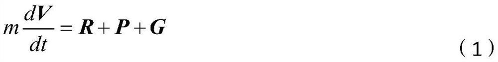
[0036]

[0037] Among them, m is the mass of the missile, dV / dt is the absolute derivative of the ground velocity vector V in the ground coordinate system, R is the aerodynamic force, P is the engine thrust, and G is the gravity.

[0038] The kinematic equation of the missile center of mass motion is established in the launching coordinate system.
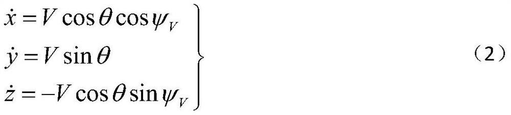
[0039]

[0040] in, are the velocity components in the three directions of x, y, and z in the launch coordinate system, V is the absolute value of the total velocity, θ is the ballistic inclination, ψ V is ...

Embodiment 2

[0056] The specific steps of an air defense missile trajectory modeling method based on the aerodynamic fixed coordinate system are as follows:

[0057] The first step is to establish the motion equation of the missile center of mass

[0058] According to Newton's second law, the dynamic equation of the missile's center of mass motion is established in the ballistic coordinate system, and the kinematic equation of the missile's center of mass motion is established in the launch coordinate system by analyzing the force of the missile.

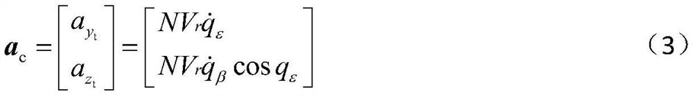
[0059] The second step is to calculate the required overload

[0060] According to the operational requirements of the missile, select the appropriate guidance law, establish the guidance relationship equation based on the relative relationship between the missile and the target, and calculate the required overload in the ballistic coordinate system. Utilizing the conversion relationship between the ballistic coordinate system and the aerodynam...


PUM


Abstract

The invention discloses an air defense missile trajectory modeling method based on a pneumatic fixed-connection coordinate system, which directly solves a balance attack angle and a balance rudder deflection angle under the pneumatic fixed-connection coordinate system and solves the problem of complex conversion of pneumatic data coordinates. The required overload under the ballistic coordinate system determined by the guidance law is subjected to simple coordinate conversion to obtain the required overload under the pneumatic fixed-connection coordinate system, and then the balance attack angle and the balance rudder deflection angle under the pneumatic fixed-connection coordinate system are obtained through an iterative algorithm; complex conversion of aerodynamic data from an aerodynamic fixed-connection coordinate system to a ballistic coordinate system in a traditional modeling method is avoided, and the calculation process is simplified.

Description

technical field [0001] The invention relates to a ballistic modeling method of an air defense missile, in particular to a ballistic modeling method of an air defense missile based on an aerodynamic fixed coordinate system. Background technique [0002] In order to simplify the expression form of the model when modeling the ballistic of the anti-aircraft missile, the dynamic equation of the center of mass motion is usually established in the ballistic coordinate system. At present, the aerodynamic data of tilt-stabilized air defense missiles are all given in the aerodynamic fixed coordinate system. When solving the trajectory, the aerodynamic data need to be converted to the missile system to calculate the balance angle of attack and balance rudder deflection angle. The calculation process is more complicated. Contents of the invention [0003] The purpose of the present invention is to provide an air defense missile ballistic modeling method based on the aerodynamic fixed ...

Claims


Application Information

Patent Timeline
Patent Type & Authority Applications(China)
IPC IPC(8): G06F30/28G06F113/08G06F119/14
CPCG06F30/28G06F2113/08G06F2119/14
Inventor 袁耀高庆丰戴磊
Owner BEIJING INST OF ELECTRONICS SYST ENG
Why Eureka
Try Eureka