Equipment having rotary pistons usable as compressors, pumps, vacuum pumps, turbines, motors and other driving and driven hydropneumatic machines

A technology of rotary piston and compressor, applied in the direction of rotary piston engine, rotary or oscillating piston engine, rotary piston pump, etc., can solve the problems of heavy equipment, expensive manufacturing, low vacuum rate, etc., to reduce friction, prolong longevity, noise reduction effect

Active Publication Date: 2016-05-18
兹沃斯拉维·米洛瓦诺维奇
View PDF5 Cites 0 Cited by
  • Summary
  • Abstract
  • Description
  • Claims
  • Application Information

AI Technical Summary

Problems solved by technology

[0006] Generally speaking, the main disadvantages of driving and driven machines of different structures are expensive, complicated manufacturing process, and bulky equipment itself
The main disadvantages of most machines of existing construction are that they are expensive to manufacture and, due to the high coefficient of friction, require regular lubrication, resulting in a relatively complex lubrication system and thus low utilization of liquid energy, eg, very complex manufacturing processes, relatively expensive Expensive and noisy compressors (standard piston compressors); pumps that use many working circuits (2 to 10 and more) to create high pressure, heavy and expensive equipment like 100-200 Bar High-pressure pumps, which are expensive and complex in process; steam turbines that require special motors to start; vacuum equipment with high-speed rotating working circuits and low vacuum rates; very complicated internal combustion engines, etc.
[0007] Searching patent documents and technical documents in this field, no similar solutions were found for the listed technical problems

Method used


Image

  • Equipment having rotary pistons usable as compressors, pumps, vacuum pumps, turbines, motors and other driving and driven hydropneumatic machines
  • Equipment having rotary pistons usable as compressors, pumps, vacuum pumps, turbines, motors and other driving and driven hydropneumatic machines
  • Equipment having rotary pistons usable as compressors, pumps, vacuum pumps, turbines, motors and other driving and driven hydropneumatic machines

Examples


Embodiment Construction

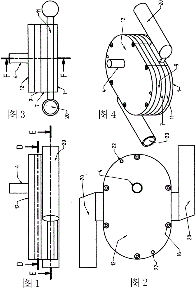
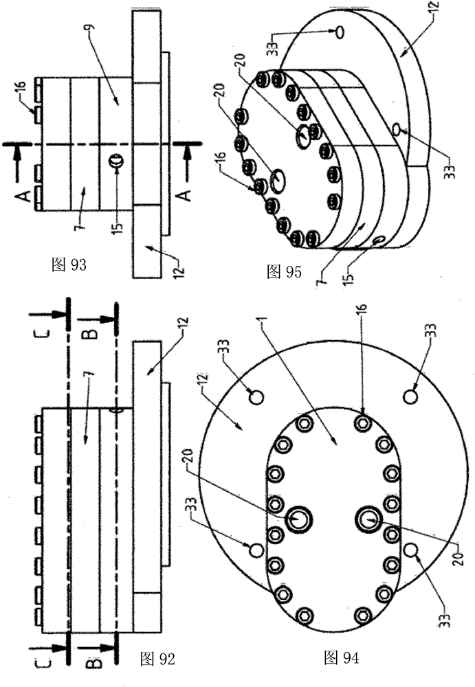
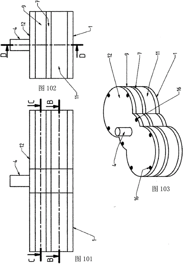
[0210] Figures 138 to 174 ,as well as Figures 1 to 137 The device in is described: a rotary piston with a cylindrical-semi-cylindrical body 6, which is integrated with the shaft, or has a hole in the center which is suitable for the diameter of the shaft, with separate or combined ( working) protrusions (A, B, C, D, E, F) or auxiliary grooves (G, H).

[0211] The one and / or several working longitudinal projections on the body 6 of the rotary piston are cylindrical-semi-cylindrical or otherwise shaped and parallel to the axis of the body 6 of the rotary piston. For easy shape identification, each shape is identified by the letter "A", "B", "C", "D", "E" or "F".

[0212] The auxiliary longitudinal groove / grooves on the body 6 of the rotary piston are cylindrical-semi-cylindrical and parallel to the axis of the body 6 of the rotary piston. For ease of shape identification, each shape is designated with the letter "G" or "H".

[0213] - (A) is a cylindrical-semi-cylindrical ...


PUM


Abstract

According to the invention, by installing gears and rotary pistons into the construction assembly, hydraulic pneumatic machines with rotary pistons, which can be used as compressors, pumps, vacuum pumps, turbines, motors and other driving and driven ones, are used in several embodiments device of. In general, depending on the type of construction, the device consists of the following components: piston housing (11) or piston housing (11a) with inlet-outlet connection (20), gear housing (9), dividing wall ( 7) or partition wall (7a), front cover (12) and rear cover (1), the above components are connected to each other by bolts which are screwed into the main body of the rear cover (1) or the main body of the piston housing (11 or 11a) , the main body of the piston housing (11 or 11a) is provided with a working-auxiliary rotary piston, which is cylindrical and has one or more working protrusions (A, B, C, D, E or F) with one or more auxiliary grooves (G or H) distributed at an angle, depending on the type of device, and the working-auxiliary rotary piston passes through shafts (4, 5) It is firmly connected with the gear (10) or gear (10a) arranged in the gear housing (9), wherein the piston housing (11 or 11a) and the gear housing (9) are separated by a wall (7 or 7a) Partition, the partition wall (7 or 7a) has holes for the shafts (4, 5) embedded in the front cover (12) and the partition wall (7) or only In the partition wall (7) or on the cover (12, 1).

Description

technical field [0001] The present invention relates to pumps with rotating pistons (or pistons) that can be used in any situation where it is necessary to create a vacuum to compress a compressible liquid or to pump a liquid, and to generate pressure (high and very high pressure) such as in vacuum pumps, compressors and pumps, It can also be used as a driving or driven hydraulic pneumatic motor, and as a device with the property of converting the energy of a certain liquid into mechanical power, such as a turbine, motor, internal combustion engine, etc., and vice versa. [0002] In general, the invention belongs to the field of: engines, turbines, transmissions, pumps, and more precisely to: machines with rotary pistons or engines, turbines, motors, pumps, according to the International Patent Classification (IPC, International Patent Classification) (2007.01) , the subject matter of the present invention belongs to the following fields, namely classified and assigned by the ...

Claims


Application Information

Patent Timeline
Patent Type & Authority Patents(China)
IPC IPC(8): F01C1/12F04C2/12
CPCF01C1/123F04C2/123
Inventor 兹沃斯拉维·米洛瓦诺维奇
Owner 兹沃斯拉维·米洛瓦诺维奇
Why Eureka
Try Eureka