Drill and method for operating a drill

A drilling and equipment technology, applied in the field of transmission devices, can solve problems such as complex drives and complex transmission devices, and achieve the effect of avoiding complex conversion

Inactive Publication Date: 2012-03-21
BAUER MASCH GMBH
View PDF3 Cites 0 Cited by
  • Summary
  • Abstract
  • Description
  • Claims
  • Application Information

AI Technical Summary

Problems solved by technology

[0006] Known drilling devices that allow adjustment of the rotational speed of the drill pipe have complex drives or complex transmissions

Method used


Image

  • Drill and method for operating a drill
  • Drill and method for operating a drill
  • Drill and method for operating a drill

Examples


Embodiment Construction

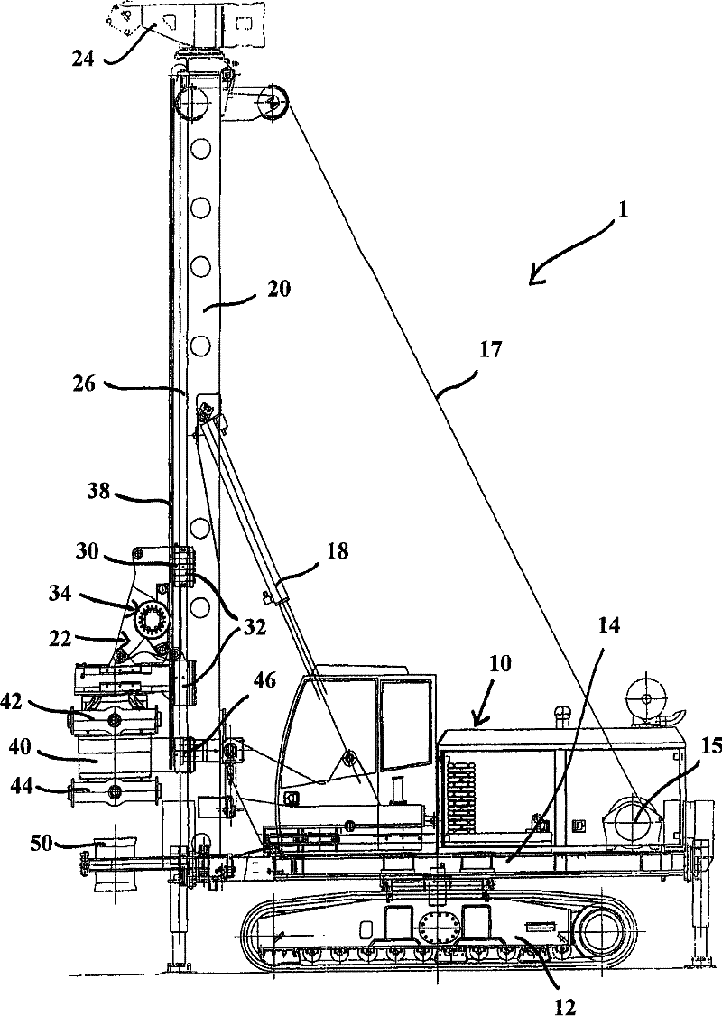
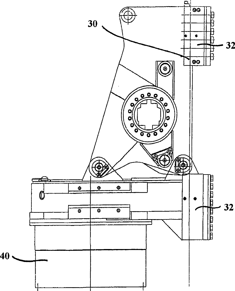
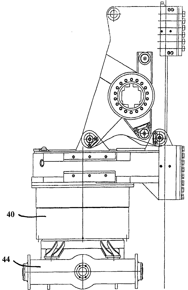
[0034] figure 1The drilling apparatus 1 of the present invention is shown with a drilling tower or derrick 20 , a bit driver 22 and a transmission 40 . The drilling rig 1 has a vehicle 10 comprising a lower chassis 12 and an upper chassis 14 articulated in rotation to the lower chassis. The mast 20 is pivotally placed on the upper chassis 14 . Via pivot cylinder 18, mast 20 is pivotable from a substantially vertical operating position to a substantially horizontal transport position. At the rear of the upper chassis 14 there is placed a winch 15 accommodating a cable 17 leading to a guide wheel located on the upper part of the derrick. The mast 20 also has a mast head 24 . In the operating position of the derrick 20 , the derrick 20 is placed in front of the front of the vehicle 10 . On the front side of the mast 20 , ie on the side facing away from the vehicle 10 , the mast 20 has a guide 26 along which the first slide 30 can be guided. The guiding device 26 has two guid...


PUM


Abstract

The invention relates to a drilling implement and a method for operating the drilling implement. The drilling implement includes a derrick, a drill drive for driving a drill rod guided on the derrick and a gear, which is placed between the drill drive and drill rod for transmission purposes. According to the invention, for inverting the gear ratio, the gear is placed in disengageable and reversible manner on the drill drive.

Description

technical field [0001] The invention relates to a drilling apparatus with a derrick or a drill tower, a drill driver guided on said derrick or derrick for driving a drill rod, and a drive between the drill driver and the drill rod for driving. transmission. Background technique [0002] Usually, such drilling equipment implements different drilling methods, or has different demands on the rotational speed and / or torque of the drill bit or the drill pipe, respectively, during the complex drilling process. [0003] One possibility to meet these different needs consists in using different drilling equipment. However, considerable expense is incurred in the complex drilling process, since for example different drilling equipment must be used for successive drilling steps. [0004] Thus, for example with known drilling equipment, the rotational speed of the drill drive can be adjusted or controlled. Thus, even for a single drilling device, different rotational speeds and torqu...

Claims


Application Information

Patent Timeline
Patent Type & Authority Patents(China)
IPC IPC(8): E21B7/02E21B15/00E21B3/02
CPCE21B3/02E21B7/02
Inventor M·萨恩K·J·克罗尔曼M·贾斯
Owner BAUER MASCH GMBH
Why Eureka
Try Eureka