
Wire harness wall-passing structure and installation method thereof

A wire harness and over-the-wall technology, which is applied to the wire harness over-the-wall structure and its installation field, can solve the problems of insufficient sealing and inapplicability, and achieve the effect of improving the sealing.

Pending Publication Date: 2021-03-12
SHENYANG POLYTECHNIC UNIV +1
View PDF0 Cites 3 Cited by
  • Summary
  • Abstract
  • Description
  • Claims
  • Application Information

AI Technical Summary

Problems solved by technology

In the second method, glue is injected into the bushing through which the wire harness passes to achieve the sealing effect, but there is still the disadvantage of insufficient sealing, which is not suitable for high-pressure vessels

Method used


Image

  • Wire harness wall-passing structure and installation method thereof
  • Wire harness wall-passing structure and installation method thereof
  • Wire harness wall-passing structure and installation method thereof

Examples


Embodiment 1

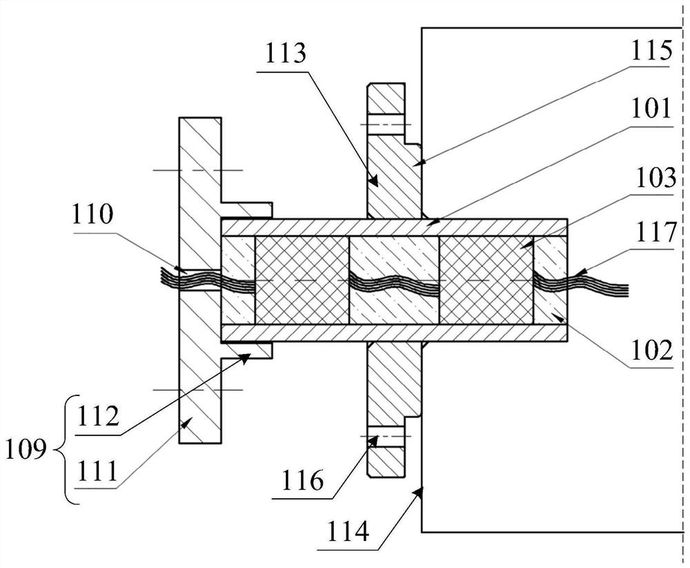
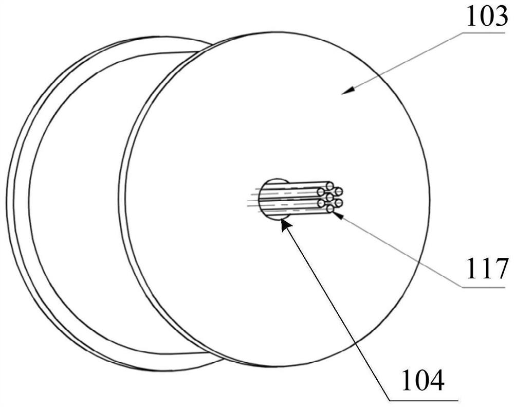
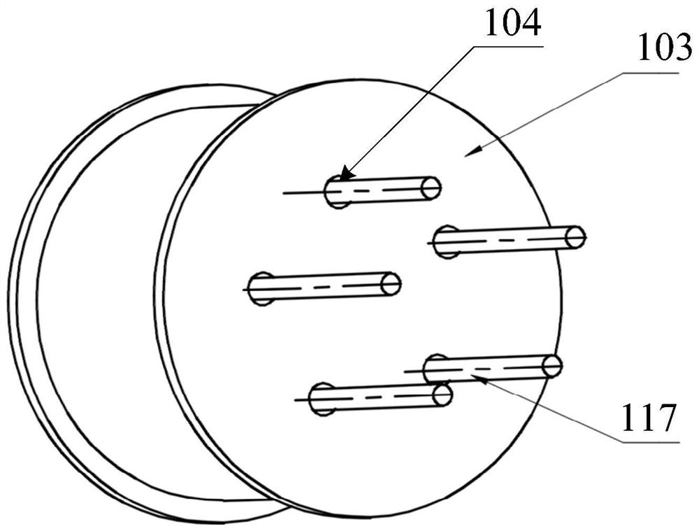
[0042] see Figure 1 to Figure 4 As shown, the harness wall structure provided by the present application includes a sleeve 101, a potting compound 102, and at least one sealing plug 103; along the axial direction of the bushing 101, the potting compound 102 and sealing plug 103 are alternately filled in the bushing 101 The sealing plug 103 is provided with at least one first through hole 104 , and the wiring harness 117 can pass through the potting compound 102 and the first through hole 104 of the sealing plug 103 .

[0043] Specifically, the wire harness passing wall structure includes a sleeve 101 , a potting compound 102 and a sealing plug 103 , wherein the sleeve 101 can pass through the wall plate of the high-pressure container waiting for the fixing device 114 . The potting compound 102 and the sealing plug 103 are arranged alternately to seal and fill the wiring cavity inside the bushing 101 .

[0044] In the specific operation, firstly, a plurality of wiring harness...

Embodiment 2

[0058] The wire harness wall-passing structure in the second embodiment is an improvement on the basis of the above-mentioned embodiment. The technical content disclosed in the above-mentioned embodiment will not be described repeatedly, and the content disclosed in the above-mentioned embodiment also belongs to the content disclosed in the second embodiment.

[0059] In the optional solution of this embodiment, at least one end of the sleeve 101 is installed with a sealing flange 109, and the sealing flange 109 is provided with a second through hole 110 corresponding to the first through hole 104, and the wire harness 117 can pass through the second through hole. Hole 110.

[0060] In this example, see figure 1 As shown, optionally, a sealing flange 109 is installed only at one end of the casing 101 outside the high-pressure vessel, so as to prevent external water vapor from entering the high-pressure vessel, and relatively save costs. Corresponding to the sealing plug 103, ...

Embodiment 3

[0072] Embodiment 3 of the present application provides an electrical device, which includes the wire harness wall-passing structure of any one of the above embodiments, and thus has all the beneficial technical effects of the wire harness wall-passing structure of any one of the above-mentioned embodiments, which will not be repeated here.


PUM


Abstract

The invention relates to the technical field of electrical equipment, in particular to a wire harness wall-passing structure and an installation method thereof. The wire harness wall-passing structurecomprises a sleeve, a pouring sealant and at least one sealing plug, the casing pipe is alternately filled with the pouring sealant and the sealing plug in the axis direction of the casing pipe; thesealing plug is provided with at least one first through hole, and a wire harness can penetrate through the pouring sealant and the first through hole of the sealing plug. According to the wire harness wall-passing structure, the casing pipe is filled with the pouring sealant and the sealing plug, so that multi-stage sealing and multi-time sealing of the wire harness are achieved, the sealing performance of the wall-passing structure is greatly improved, and the wire harness wall-passing structure is more suitable for fixing devices such as a high-pressure container.

Description

technical field [0001] The present application relates to the technical field of electrical equipment, in particular to a wire harness wall passing structure and an installation method thereof. Background technique [0002] Most of the modern high-voltage vessel systems integrate different electrical equipment. The equipment is connected by wire bundles to transmit electric energy or electrical signals. The wire bundles need to be transmitted between different high-voltage vessels through the wall. High-pressure vessels often have certain requirements for airtightness and watertightness. [0003] The current wall-passing structure of the wire harness is generally the following two types: the wire or the wire harness passes through the wall alone and the wire harness passes through the container wall using a sleeve. In the second method, glue is injected into the bushing through which the wire harness passes to achieve sealing effect, but there is still the disadvantage of i...

Claims


Application Information

Patent Timeline
Patent Type & Authority Applications(China)
IPC IPC(8): H02G3/22F16L5/02
CPCH02G3/22F16L5/02H02G15/013F16L5/14F16L5/08
Inventor 赵晶崔剑征王世杰张擎宇张俊飞张宪伟
Owner SHENYANG POLYTECHNIC UNIV
Learn More