
Patsnap Eureka
For R&D, Patsnap Eureka makes reading and utilizing patents & technical documents easy.
Patsnap Eureka AIR
Designed for self-driven R&D workflows. Generate viable solutions, solve complex R&D challenges, empower your innovation with AI.

Patsnap Eureka Materials
Designed for material experts only. Revolutionize your material R&D, from search, analyze, to developing new materials.

TechResearch
Generate reliable direction feasibility study reports for your R&D in just a few steps.

TechSeek
Discover and master advanced knowledge NOW. Basics, ideas, possibilities, all at once.

TechMind
As an expert in R&D Theories, TechMind can generates customized viable solutions instantly.

TechRisk
Analyze your overall solution with one click, know your potential R&D risks in advance.

TechMonitor
Get weekly tech updates, stay abreast of the latest tech innovations and key insights.
Automatic desulfurization ceramic equipment
A ceramic and automatic technology, applied in gas treatment, dispersed particle separation, membrane technology, etc., can solve problems such as loss of gas push, air pollution of sulfur gas, and difficulty of gas passing through the separation layer upwards
- Summary
- Abstract
- Description
- Claims
- Application Information
AI Technical Summary
Problems solved by technology
Method used
Image

Examples
Embodiment 1
[0026] For example figure 1 -example Figure 5 Shown:
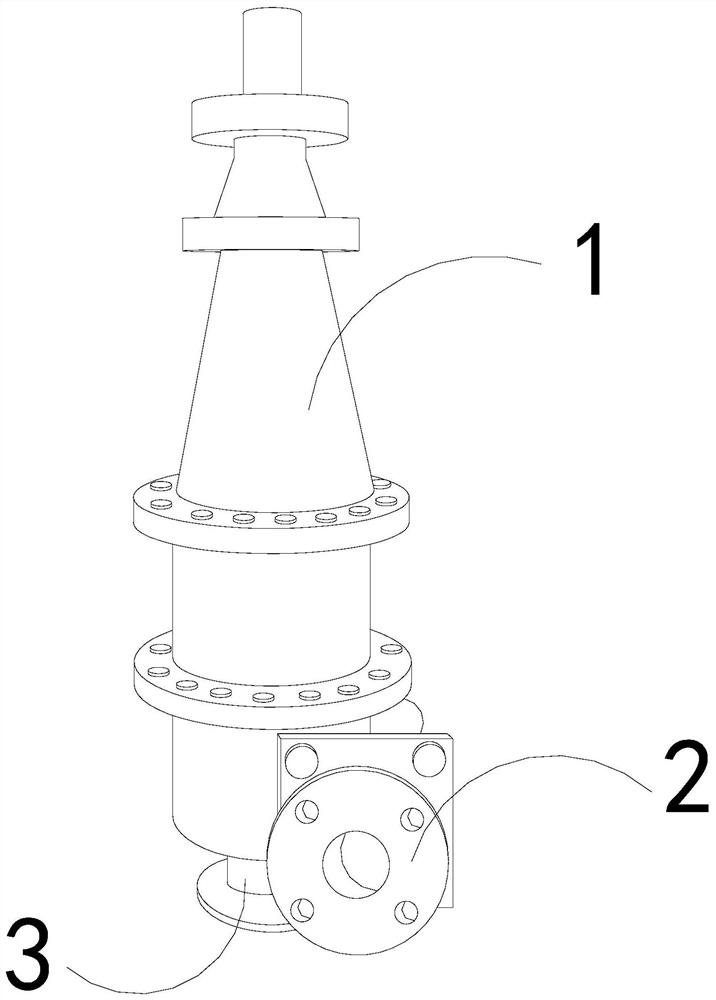
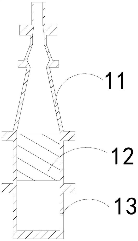
[0027] The present invention provides an automatic desulfurization ceramic device, the structure of which includes a body 1, an air inlet pipe 2, and a base 3, the air inlet pipe 2 and the body 1 are of an integrated structure, and the body 1 and the base 3 are of an integrated structure; The body 1 includes an outer frame 11 , a separation layer 12 , and an air vent 13 , the separation layer 12 is embedded in the inner position of the outer frame 11 , and the air vent 13 and the outer frame 11 are an integrated structure.
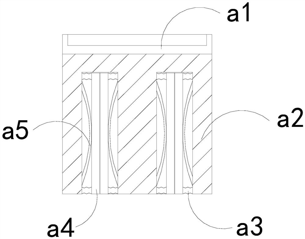
[0028] Wherein, the separation layer 12 includes an air suction mechanism a1, a filter plate a2, a linkage block a3, a closing plate a4, and a booster piece a5, and the air suction mechanism a1 is embedded in the upper end of the filter plate a2, and the linkage block a3 is installed between the closing plate a4 and the filter plate a2, the closing plate a4 is movably engaged with the filter plate a...
Embodiment 2
[0034] For example Figure 6 -example Figure 8 Shown:
[0035] Wherein, the closed plate a4 includes an overhanging plate c1, a plate surface c2, and an elastic piece c3, the outreaching plate c1 and the plate surface c2 are in clearance fit, and the elastic piece c3 is installed between the overhanging plate c1 and the plate surface c2 Among them, there are five outrigger plates c1, which are evenly distributed in parallel on the board surface c2, and the outrigger board c1 that loses object extrusion can be pushed out along the board surface c2 through the elastic piece c3.
[0036] Wherein, the outreach plate c1 includes an outboard expansion plate c11, an elastic ring c12, and a receiving plate c13. , and are evenly distributed symmetrically at the upper and lower ends of the right side of the receiving plate c13, and the outer expansion plate c11 that has lost the inner wall of the object can be pushed outward by the elastic ring c12.
[0037] Wherein, the receiving p...
PUM
 Abstract
Description
Claims
Application Information
 - R&D Engineer
- R&D Manager
- IP Professional
- Industry Leading Data Capabilities
- Powerful AI technology
- Patent DNA Extraction
Browse by: Latest US Patents, China's latest patents, Technical Efficacy Thesaurus, Application Domain, Technology Topic, Popular Technical Reports.
© 2024 PatSnap. All rights reserved.Legal|Privacy policy|Modern Slavery Act Transparency Statement|Sitemap|About US| Contact US: help@patsnap.com